Do you have a question about the Norcold N10DCX and is the answer not in the manual?
Provides maintenance, diagnostic, and repair information for N10DCX.
Details compliance with UL 60335-1 standards and UL compliance.
Covers installation requirements for warranty and local codes.
Emphasizes using authorized NORCOLD® parts for safety and reliability.
Provides contact information for technical support inquiries.
Lists electronic features like ON/OFF, Mode, Temperature Set, LED indicators.
Specifies the required dimensions for installation.
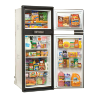
States the total internal volume of the refrigerator.
Details DC input voltage, cut-out, and cut-in requirements.
Specifies fuse rating and amperage for fans/light.
Defines the maximum tilt angles for operation.
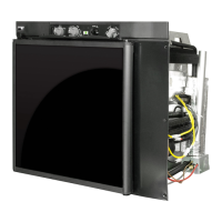
Identifies components in the front view exploded diagram.
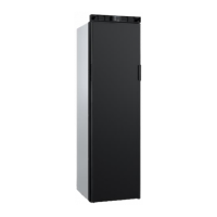
Identifies components in the rear view exploded diagram.
Confirms adequate ventilation, safe electrical components, and proper mounting.
Explains the importance of airflow for cooling performance and system longevity.
Details requirements for independent 12V DC supply and proper wiring.
Instructs on correct connection of positive and negative DC leads.
Basic checks before performing detailed diagnostics, ensuring proper operation.
Lists reference numbers and descriptions for LED indicators and connectors.
Lists necessary items for conducting self-diagnostics with LED.
Provides step-by-step instructions for connecting the LED for diagnostics.
Maps LED flash counts to specific error conditions and tests.
Links common refrigerator symptoms to possible causes and corrective tests.
Lists fault codes, their meanings, and corresponding actions.
Guide for diagnosing issues related to the compressor control module.
Procedure to check DC supply voltage and cut-out function.
Procedure to diagnose issues with the fan over current cut-out.
Procedure to diagnose motor start errors and system pressures.
Procedure to diagnose if the motor fails to maintain minimum speed.
Procedure to diagnose if the electronic unit overheats and triggers thermal cut-out.
Procedure to diagnose why the refrigerator is not cooling or turning on.
Procedure to diagnose if the refrigerator is cooling excessively.
Procedure to diagnose excessive frost buildup inside the refrigerator.
Procedure to diagnose if the refrigerator runs but cools inadequately.
Procedure to diagnose why the refrigerator is not operating on DC power.
Diagnoses refrigerator cut-outs despite voltage being within range.
Diagnoses the fresh food thermistor cycling issue.
Diagnoses the freezer thermistor cycling issue.
Addresses issues with DC input voltage being outside the cut-out setting.
Diagnoses issues related to the fresh food compartment door being open too long.
Illustrates the electrical connections and components of the refrigerator.
Steps for safely disconnecting and removing the refrigerator from its enclosure.
Steps for reinstalling the refrigerator into its enclosure.
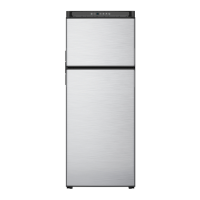
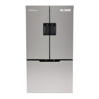
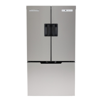
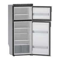
| Style | Top Freezer |
|---|---|
| Color | Stainless Steel |
| Number of Doors | 2 |
| Total Capacity | 30 |
| Refrigerator Capacity | - |
| Freezer Capacity | 5 |
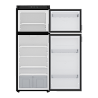
| Number of Refrigerator Shelves | - |
| Number of Refrigerator Bins | 7 |
| Humidity Controlled Crispers | - |
| Number of Freezer Shelves/Baskets | - |
| Refrigerator Temperature | - |
| Freezer Temperature | - |
| (-14°C) | - |
| Refrigerator Special Features | 2-Minute Door Alarm |
| Freezer Special Features | - |
| Defrost System | Manual |
| Noise level | - |
| Refrigerant | - |
| Energy Class | - |
| Annual Energy Consumption | - |
| Voltage | - |
| Frequency | - |
| Current | 15 A |
| Depth | 29 5/8 in |
|---|---|
| Height | 70 1/8 in |
| Width | 36 in |
| Net Weight | 65 lbs |