EasyManua.ls Logo

Nordyne B6BM Series User Manual

Nordyne B6BM Series
32 pages
To Next Page IconTo Next Page
Page #1 background imageLoading...
Page #1 background image
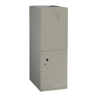
AIR HANDLER
B6BM, B6EM, & B6VM SERIES
INSTALLATION INSTRUCTIONS
IMPORTANT
ATTENTION INSTALLERS:
It is your responsibility to know this product better than your customer. This includes being
able to install the product according to strict safety guidelines and instructing the customer on
how to operate and maintain the equipment for the life of the product. Safety should always be
the deciding factor when installing this product and using common sense plays an important
role as well. Pay attention to all safety warnings and any other special notes highlighted in the
manual. Improper installation of the furnace or failure to follow safety warnings could result in
serious injury, death, or property damage.
These instructions are primarily intended to assist qualified individuals experienced in the proper
installation of this appliance. Some local codes require licensed installation/service personnel
for this type of equipment. Please read all instructions carefully before starting the installation.
Return these instructions to the customer’s package for future reference.
DO NOT DESTROY. PLEASE READ CAREFULLY & KEEP IN A SAFE PLACE FOR FUTURE REFERENCE.
Questions and Answers:

Nordyne B6BM Series Specifications

General IconGeneral
ModelB6BM Series
TypeAir Handler
SeriesB6BM
Voltage208/230V
Phase1

Summary

IMPORTANT SAFETY INFORMATION

REQUIREMENTS & CODES

GENERAL INFORMATION

Locating the Air Handler

Determining the optimal placement for the air handler unit within the installation space.

Minimum Clearances

Specifies required clearances around the unit for proper operation and maintenance access.

Installation in a Garage

Guidelines for installing the air handler in a residential garage environment.

Plenums & Air Ducts

AIR HANDLER INSTALLATION

Packaging Removal

Instructions for safely removing the air handler from its shipping packaging.

Mounting Applications

Details on various mounting configurations for the air handler unit.

Upflow Installations

Procedure for installing the air handler in an upflow airflow configuration.

Downflow Installations

Procedure for installing the air handler in a downflow airflow configuration.

Horizontal Installations

Guidelines for installing the air handler in horizontal airflow configurations.

Horizontal Left Installations

Specific steps for horizontal installation with airflow to the left.

Horizontal Right Installations

Specific steps for horizontal installation with airflow to the right.

Circuit Breaker Cover Installation

Instructions for installing the protective cover for circuit breakers.

Refrigerant Line Connections

Orifice Removal & Installation

Steps for replacing or verifying the refrigerant metering device orifice.

Connecting the Linesets

Detailed instructions for brazing and connecting refrigerant linesets.

Condensate Drainage

ELECTRICAL CONNECTIONS

Pre-Electrical Checklist

Pre-installation checks for electrical system compatibility and readiness.

Line Voltage

Details on connecting the main power supply to the unit.

Thermostat Connections

Instructions for wiring the thermostat to the air handler.

Grounding

Procedure for ensuring proper electrical grounding of the unit.

Control Board

Information about the function and operation of the control board.

STARTUP & ADJUSTMENTS

Before You Start the Unit

Essential checks and preparations before powering on the unit.

Twinning

Instructions for connecting two air handlers to a single outdoor unit.

Heater Kits

Installation procedures for electric heater kits.

Humidifier

Wiring instructions for connecting a humidifier.

Dehumidification Options

Configuration for enhanced humidity removal using the system's features.

Electronic Air Cleaner (EAC)

Wiring instructions for connecting an electronic air cleaner.

Air Circulation

Adjusting and verifying airflow for optimal system performance.

Blower Configurations

Setting up the blower speed and airflow based on system needs.

REFRIGERANT CHARGING

UNIT MAINTENANCE

TROUBLESHOOTING

WIRING DIAGRAM

WIRING DIAGRAM Air Handler with Fixed Speed High Efficiency Motor

WIRING DIAGRAM Air Handler with Variable Speed High Efficiency Motor

INSTALLATION CHECKLIST

Related product manuals