•
•
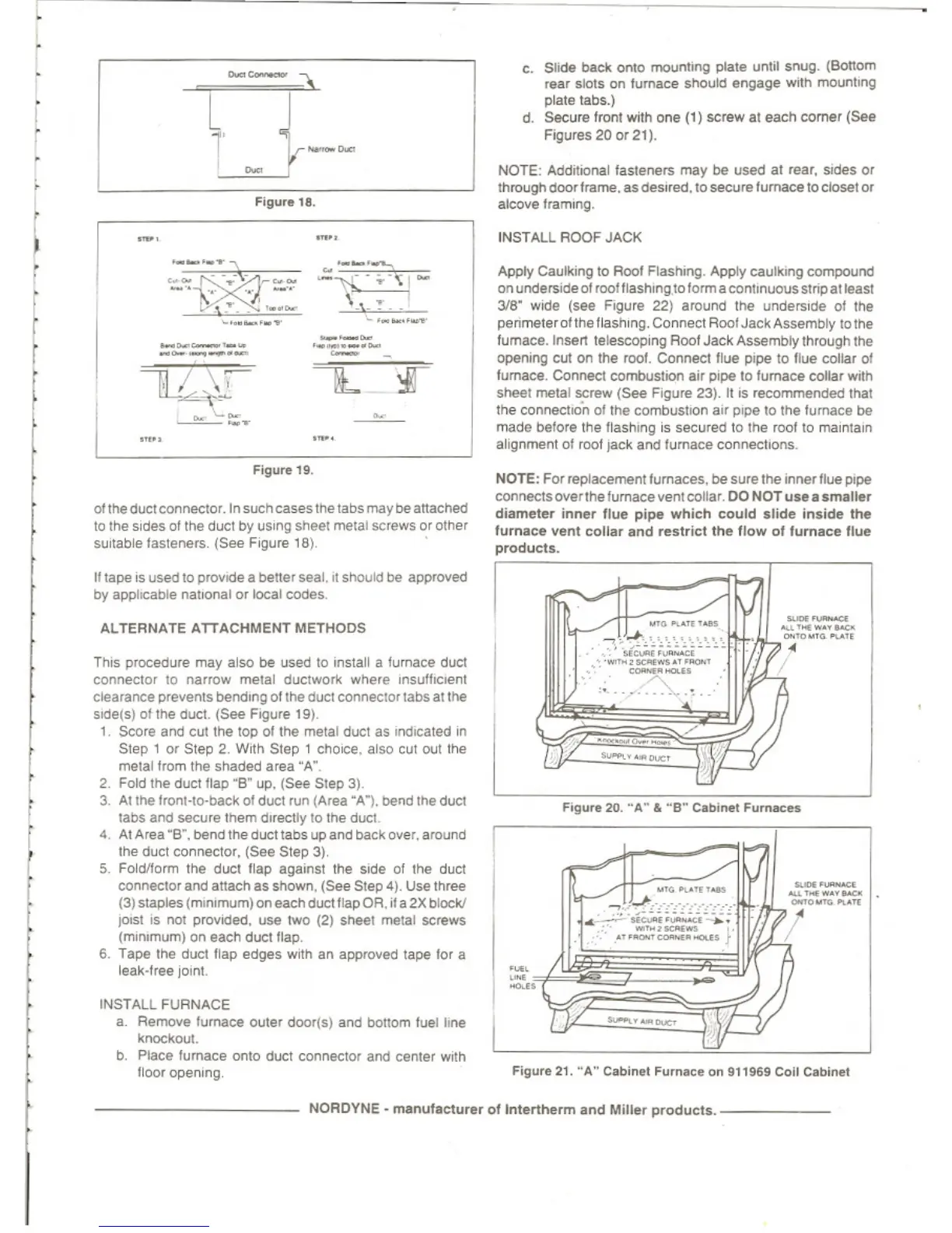
INSTALL ROOF JACK
c Stide
bacl<
01'10
m:lOnli"ll
plale untit snug. (Bot1om
"'Ilr
stolS on
lumace
should e"<Jall€' with mount''''J
plate 18bs.)
d. Secure front with ooe (1) screw al
each
comer
(Set!
Figu,es
20
or
2t),
Apply Caulkmg to Roof FlashIng. Apply caUlkIng
compDl'n(!
on
Underside
of
rootflashing,
lD
form acon\lnuous
st
npatleasl
3/B" wKle
(see
Figure 22) around
the
unde""de
of the
penmelerofthe Hasnln9, Connect Rool
Jack
Assembly
to
Ihe
fumace.lnsell
telescop<ng
ROOf
Jack
Assemblylhrough
tile
opelll"ll
CUI
on the rool. Connect flue ll'Pl! 10 llue coHar
of
fumace, Connect combustIOn air
P<Pl!
to
lumac
.. collar with
sheet melal
SCrew
(See
Flgufe 23). II is rocommende<! that
the
connection of
the
combuSlIon
alf
p,pe to the Iurnace be
maoe
betore the flashIng is secUfeo to
tt>e
roof
10
maintain
alignment
01
roof jack and turnace COflIlllCIIOIlS.
NOTE: Addiloonallasteners
may
be
used
al
rear,
SlOeS
or
T1lfOUgh
(100<
frame.
as
(les"ect,10 secure
lurnace
to closet
or
aICO"" framIng.
..
-
............
-",,-';."-;
...
\.\_'!"-
'
..
~-."",
---
'._'_.-
-
--v.R2,.t-
_
..
~
-'.
".'
'0"
_.
•
,"
-
......
---'-"
---_.-
u-~
~
r
f
Figure
1lI.
Olille
dllC1
conne<:lO'. In
such
CaseS too
tabs
may
be
attached
to
the
sides
01
the
duct
by
USing
sheel
melal
screws
or other
sUitable
lasteners.
(See
F
'gure
18)
NOTE: Forreplacement lumaces,
bes"re
the
Innerllue
pipe
connects
overlhe
fumace vent collar.
00
NOT
uae
..
amaller
diameler
inner
Ilue
pipe
Which
could
alid
..
inside
lhe
lurnace
vent
collar
and
reslricllhe
Ilow
01
lumac
..
lIue
producls.
FiGure
21.
"A"
Callin..t
Fum""
.. on
"196'
Coil Ceblnel
--
....
'
......
y'"""
'""OM",
"."
•
--
...
'
...
w
••
'"""
""toM'
.....
"
IIJI'
•
"'
....
.,,,-
-,.
~o~"~"'_
.,~~~
•
«_
'..-.co
~"',"""'ws
."
....
'
"""/:
""'
..
."-.-
...
C>
.
'"""
.-"0,,,,_,,,,
...
_
..
c..ooo_.
~.
"
~"""",,,WS
.,,""",
=-0.
_
..
}
."
Figure
20.
-A"
&
-B"
Ceblnel Furn..:
..
It tape IS
Use<110
provide a
bene'
seal.
,t
should
be
approved
by
applicable natKlOllI
Of
lOCal
codes
Til,s procedure
may
also be used
10
,nstall a furnace
dUel
ccmnector 10 narrow
melal
dUClwor1<
whe'e
Insulh"",n1
c~a,ance
prevents bending
of
lhe
Que!
ccone<:IO'
tabs
at the
sKleis)
01
the
duct
(See
F'!lure 19)
1 SCore
and
Cui the top
01
the
metal
duct
as
IndICated
,n
Slep'
or
Step 2. With Slep ,
chOICe.
also cut
001
the
melal from the shaded
a,ea
"A"
2 Fold the duct
Hap
-go
up.
(See
Step 3l
3.
At the
fronHp·Di!ck
of
dUCI
run
(Area
"A"),
oer>d
the
dUCI
labs
and
secUfe u
....
m
d<re<:lly
to
the
duel
4
At
Area "S",
bend
the dUCl1abs up
an<!
back
o"e"
around
'he
duct
connectO'.lSet!
Step 3),
5.
Foict/lorm the
duel
flap
a'1a"ut
the
sode
ot the duet
COMedO,
an<!
attach as
s!>Own,
(Set! Step 4). UseIh,,,,,
(3) staples (mlnomum) on each duct flap OR.
~
a
2X
block/
""st
is
1101
p<0\fItIe<l. use two (2) Sr.eel metal screws
(minImum) on each
duct
llap.
6.
Tape
the duel flap edges
With
an approved tape tor a
leak·f,ee
jomt
ALTERNATE
ATTACHMENT
METHODS
INSTALL FURNACE
a. Remove furnace
oute,
doorlsj
an<!
b<:1lI0m
tvet tIne
knockout
b,
Place fumace onlO duct connectO' and center
w~h
floo, opening
NORDYNE·
manufactu,er
of
tnlertf\erm
and
Millar
producls.
_
 Loading...