NORIS Automation GmbH, Friedrich-Barnewitz-Str. 10, D -18119 Rostock
phone: +49 381 519944-0, fax: +49 381 519944-4, info@noris-automation.de
NAR-KD-0151-1-en
V. 1.01 - 04/07/16
page 4 of 9
1 Introduction
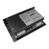
The servo controller SG 2000 is provided to control hydraulic proportional valves
with 2 solenoids and without position control.
The device is to be mounted in electrical cabinets or terminal boxes. It will be
mounted with 4 screws directly at the mounting plate.
Input signal - +/-10V DC as setting value
- dry contact (NO) or +24V as enable signal
output: - 2 proportional solenoids I
max
= 1,5A
- Dry contact „Failure“ (NC)
- Measuring outputs for setting and actual current (0-
10V)
Power supply: - 24V DC +30/-25%
Signal-LED: - LED 1 green - no failure
- LED 2 red - control loop fault
- LED 3 red - voltage too low
- LED 4 green - auxiliary voltage o.K.
- LED 5 yellow - current limitation
2 Function
The controller works with 24V DC at the terminals 13 and 14. At terminals 1 and 2
the setting value of +/- 10VDC should be provided. If the enable signal at terminal 7
is present, the actual setting value is performed into a proportional current and
feeded to the corresponding proportional solenoid, depending from the polarity of
the input signal. The current is measured and controlled. The control of the
solenoids is made as a PWM-signal. A so called jitter frequency, which is overlayed
to the output current ensures, that the pistons of the valves will not glue. Depending
from the polarity of the input signal, only the corresponding amplifier is switched on.
The calibration of the output current is made by the manufacturer.
A failure output is performed in case of:
- Power supply voltage too low
- Auxiliary supply +15V is not present
- Failure in control loop (e.g. short circuit or wire
braek)
At terminal 5 and 6 the actual current and the desired current can be measured as a
0 – 10V voltage.

 Loading...