Do you have a question about the NORSELIGHT XS 500 R60 and is the answer not in the manual?
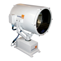
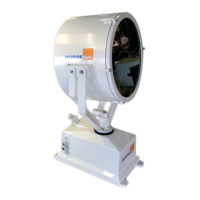
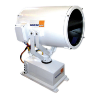
Describes the R60 searchlights construction and components.
Details functions of Main Operation Panel R60, R50/R60, and Slave Operation Panel.
Explains the Access Point for wireless control of searchlights.
Lists benefits like weatherproof casing, TCP/IP technology, and offshore suitability.
Lists the wireless receiver unit, PoE power supply, and antenna.
Details functions like power on/off, touch controls, speed regulation, and focus adjustment.
Lists programmable dimming, focus indicator, and temperature alarm.
Lists RAL colors, mounting options, and special cable glands.
Lists IP classification, ambient temperatures, movement ranges, and color.
Details article number, model, wattage, voltage, and body material for XS models.
Lists IP classification, temperature, input voltage, connection bus, dimensions, weight, and power consumption.
Lists IP classification, connection signals, dimensions, and weight.
Lists IP classification.
Lists IP classification and input voltage.
Details IP, ambient temp, input voltage, cable diameters, dimensions, and weight.
Details IP, ambient temp, input voltage, dimensions, and weight.
Details IP, ambient temp, input voltage, cable diameters, dimensions, and weight.
Details IP, ambient temp, input voltage, cable diameters, dimensions, and weight.
Details IP, ambient temp, input voltage, cable diameters, dimensions, and weight.
Details IP, ambient temp, input voltage, cable diameters, dimensions, and weight.
Provides dimensional data and cable entry specifications for XS 500-2000 models.
Provides dimensional data and cable entry specifications for the XS 3000 model.
Provides drilling template dimensions for the main joystick panel installation.
Provides drilling template dimensions for the slave panel installation.
Shows physical dimensions (A, B, H) for the EX-30 G/1 power supply.
Shows physical dimensions (A, B, H) for the PX-50N power supply.
Shows physical dimensions (A, B, H) for the NP-0725 power supply.
Explains SW1 position for remote ON/OFF and SW2 for power selection.
Details the procedure to reset the power supply after overheating shutdown.
Shows physical dimensions of the NP-0725 with heat sink.
Notes that current adjustments are made while the bulb is switched on.
Shows physical dimensions (A, B, H) for N3-80E and N3-150E.
Safety warnings for electrical installation, polarity, grounding, and required connections.
Lists synoptic panel, terminal blocks, and connectors for control.
Shows the front panel layout with dimensions.
Shows the bottom panel layout with dimensions.
Explains parameter settings like Pmax, Imax, Imin, and stand-by for EX-100 D/1.
Notes on entering Imax values lower than Imin or exceeding Imax.
Table detailing Pmax, Imax, Imin, stand-by, and set-point for different wattages.
Flowchart illustrating parameter setting steps for a 3000W Xenon lamp.
Continues the flowchart for parameter setting, including password change.
Indicates the transition to mode setting after parameter configuration.
Explains how to operate the searchlight using the synoptic panel in manual mode.
Important note regarding forced switching in manual mode from remote control.
Initiates the flowchart for selecting and configuring parameter modes.
Path in the flowchart for selecting the Ext 10V mode.
Path in the flowchart for selecting the last used program.
Path in the flowchart for selecting the manual program mode.
Path in the flowchart for selecting the RS232 only program mode.
Path in the flowchart for ON/OFF mode selection via remote.
Path in the flowchart for ON/OFF mode selection via synoptic panel.
Emphasizes disconnecting power, authorized personnel, polarity check, and grounding.
Diagram showing connection of B2 searchlight to NP-0752 power supply.
Shows connections to the B1 main panel.
Shows connections to the slave panel.
Shows connections to the Panel PLC module.
Details cable numbers, use, type, from, and to for system layout.
Shows connections to the B2 searchlight unit.
Shows connections to the B1 main panel.
Shows connections to the slave panel.
Shows connections to the Panel PLC module.
Details cable numbers, use, type, from, and to for system layout.
Shows connections to the touch panel.
Shows connections to the power supply unit.
Shows connections to the switch.
Shows connections to the filter.
Shows connections to the panel PLC input.
Shows connections to the B2-A1 LAN interface.
Shows optional wiring for remote signal to the rectifier.
Instructs to set the switch to "0" for remote control operation.
Shows connections for mains input, lamp, and igniter.
Shows connections for AC input and lamp output.
Guides on setting switches and adjusting current for 50A.
Identifies the NP-0725 power supply and its spare part number.
Shows connections for various signals like Failure, Alarm, and Remote ON/OFF.
Illustrates the wiring and connections for the N3-80E and N3-150E power supplies.
Shows input and output terminal connections for the power supplies.
Shows connections for output, input, RS-232, and 0-10V interfaces.
Specifies the default password for accessing settings.
Details steps for first start-up and actions after power loss, including calibration.
Shows the main controller panel interface for managing searchlights.
Displays the screen for entering the password to access settings.
Guides on selecting and enabling all searchlights within the system.
Instructions on how to start the hardware settings process from the home menu.
Shows the password screen for accessing hardware settings.
Describes how to select individual searchlights from the home menu for configuration.
Guides on selecting multiple searchlights for system-wide settings.
Explains how to set the installation orientation (0-point) for the searchlight.
Refers to drawing E-R60-027 on page 57 for slave panel wiring.
Shows the main settings screen for the slave panel.
Displays specific settings available for the slave panel.
Lists selectable settings like reverse direction, speed, and panel enable.
Describes settings for the software joystick via the main menu.
Details settings for the hardware joystick on the main panel.
Details settings for the hardware joystick on the slave panel.
Mentions the analog proportional joystick and its separate manual.
Shows the interface for configuring joystick settings on the main panel.
Shows the interface for configuring joystick settings on the slave panel.
Introduces the software menu for controlling searchlight functions and feedback.
Directs to page 38 for information on the help menu.
Points to information about searchlight signals.
Directs to searchlight settings information.
Directs to page 36 for the Home menu.
Directs to page 37 for Home1 position settings.
Directs to page 37 for sweep settings.
Directs to page 37 for sweep limits.
Explains lamp on/off control and dim function.
Describes the focus position indicator (0-100).
Explains how to control focus in and out.
Directs to page 33 for vertical angle indicator settings.
Refers to a pop-up for vertical speed information.
Explains how to choose the searchlight to control.
Refers to a pop-up for horizontal speed information.
Directs to page 33 for horizontal position indicator settings.
Explains the symbol used for ship reference.
Directs to page 34 for joystick settings.
Directs to page 37 for mechanical stop indicator settings.
Instructs to press the Home button to access the Home menu.
Explains how to select and control up to 9 searchlights.
Notes that the panel can be dimmed in 32 levels via a pop-up menu.
Describes I/O information on the Panel PLC, with yellow indicating logic ON.
Shows the screen for setting horizontal and vertical movement limits.
Warns against exceeding movement limits of -180 and 180 degrees.
Shows the screen for setting sweep limits and home positions.
Guides on setting min/max sweep degrees for horizontal movement.
Guides on setting min/max sweep degrees for vertical movement.
Guides on setting horizontal and vertical parking for Home position 1.
Guides on setting horizontal and vertical parking for Home position 2.
Clarifies that min/max degrees/positions are limited by sector limits.
States that the Help menu is available in most menus.
Shows I/O information, explaining input and output numbers and their states.
Lists input signals for the PLC, such as joystick and switches.
Lists output signals from the PLC, such as motor directions and lamp status.
Displays the current status of inputs and outputs for a selected searchlight.
Explains settings for the area where the searchlight can move.
Explains joystick reverse direction, speed, and slave panel enable.
Displays version information for Panel 1.
Shows the location of the alarm indicator on the control panel.
Displays example alarm text, searchlight number, and status colors.
Explains how alarm text displays searchlight number and alarm type.
Defines status codes: Red (unacknowledged), Green (unacknowledged), Yellow (acknowledged).
Instructs on how to acknowledge and delete inactive alarms.
Indicates the presence and use of a scrollbar for the alarm list.
States that guarantee is valid only against production faults, not damage.
Emphasizes using safety equipment and cutting power before working.
Warns against cleaning the searchlight with high pressure.
Lists recommended maintenance intervals for 6 months, 1 year, and 3 years.
Specifies the recommended grease type and temperature range.
Advises checking screws to ensure proper moveability.
Lists part numbers for Xenon R60 searchlights across different models.
Details safety measures and initial steps before replacing the lamp.
Instructs on removing nuts holding the front glass.
Guides on loosening bolts to remove the lamp holder bracket.
Suggests using a small screwdriver if needed to loosen the bracket.
Instructs on removing the lamp holder bracket.
Details loosening the bolt for the positive lamp connector.
Guides on using a flat screwdriver to release the connector.
Instructs to unscrew the lamp by hand.
Guides on installing the new lamp and tightening by hand.
Details pushing and tightening the positive connector.
Instructs on re-installing the lamp holder bracket.
Guides on re-installing the front glass to complete the process.
States that batteries can be changed in the PLC within the panel or searchlight.
Details steps for replacing the battery in the PLC, including connector handling.
Details steps for replacing the battery in the control panel unit.
Describes resetting the lamp counter after lamp replacement and alarm limit adjustment.
Warns about UV radiation and keeping clear of hot components.
Refers to attached operating instructions for lamp disposal.
Guides on disconnecting the battery connector and replacing the battery.
Clarifies that the battery is used exclusively for securing firmware.
States that data sheets for the battery are available upon request.
Provides causes and checks for searchlight not moving horizontally or vertically.
Lists checks for issues when the light does not turn on.
Suggests checks for when the focus function is not working.
Lists checks for communication errors in the main menu.
Explains the issue of two persons controlling the same searchlight.
Details what damages are not covered by the warranty.
Instructs on claim handling and contacting customer service.
Shows the +24V DC power connection to the PLC.
Details the wiring for slave joystick inputs.
Shows wiring for the slave ignite input.
Shows the B2-A1 PLC input terminal block.
Shows the +24V DC power connection from the integrated PSU.
Details wiring for motorhouse joystick inputs.
Shows wiring for the motorhouse slave ignite input.
Shows the connection to the premium power supply unit.
Shows the B2-A1 PLC output terminal block.
Shows the output for remote lamp on/off control.
Shows the output signal for the ignitor.
Shows the output for focus on/off control.
Shows PWM and direction outputs for the vertical motor.
Shows PWM and direction outputs for the horizontal motor.
Shows wiring connections for the slave panel.
Shows wiring connections for the B1 main panel.
Shows wiring connections for the Panel PLC module.
Details cable numbers, use, type, from, and to for system layout.
Shows wiring for the vertical, horizontal, and focus motors.
Details connections to the PLC B2-A1 interface.
Shows wiring for motors when using PX-50 PSU.
Details PLC B2-A1 connections with PX-50 PSU.
Shows connection to the premium power supply in the motorhouse.
Details wiring for motors connected to the motorhouse PSU.
Shows connections for the Xenon power supply B2-T1.
Details wiring for heating elements and cables.
Shows wiring for the focus motor.
Details wiring for heating elements and cables.
Shows wiring for the focus motor.
Shows wiring for the ignitor.
Shows the +24V DC power connection for the slave panel.
Details wiring for slave joystick inputs on panel B6.
Shows wiring for the slave ignite input on panel B6.
Lists IP addresses for searchlights, wireless remotes, panels, and controllers.
Provides step-by-step instructions for making a LAN cable.
Specifies the required LAN cable type (4pair STP/FTP min)cat5E.
| Power | 500W |
|---|---|
| Luminous Flux | 65000 lm |
| IP Rating | IP66 |
| Beam Angle | 60° |
| Frequency | 50/60Hz |
| Lifespan | 50, 000 hours |
| Material | Aluminum |
| Color Temperature | 3000K |