25 | Installation
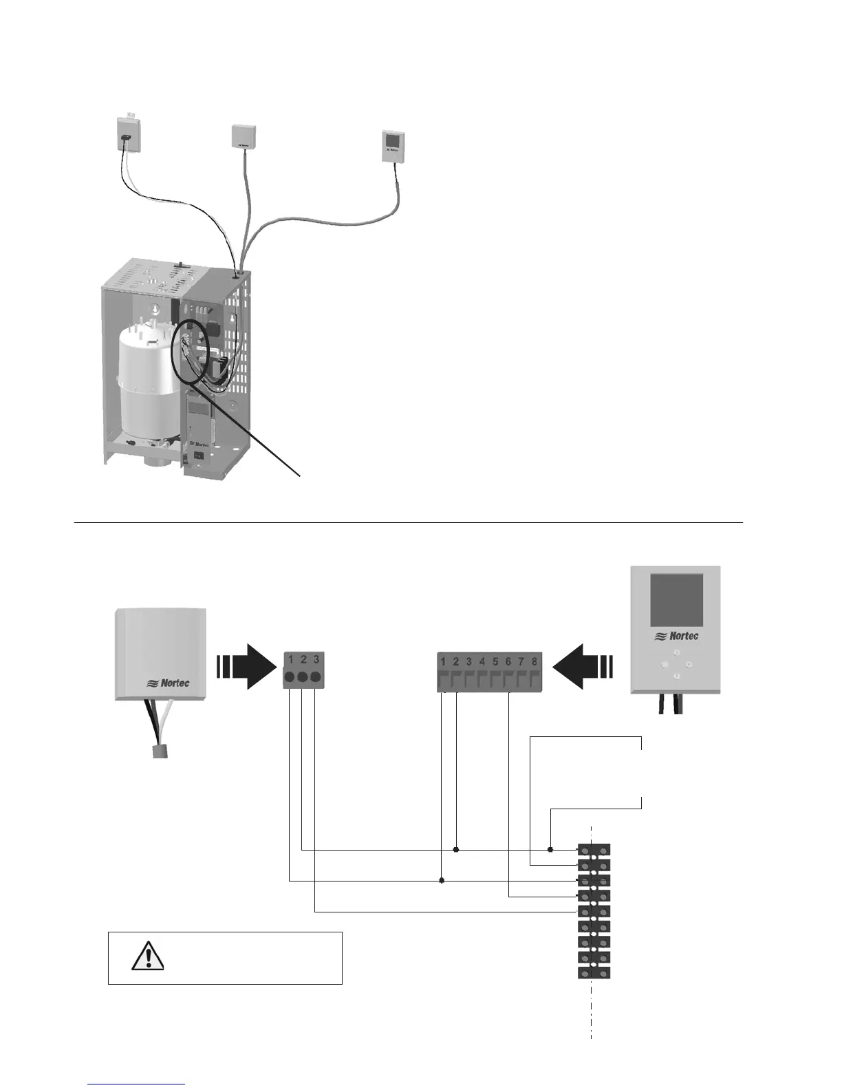
Transducer Control Wiring (NHTC Only)
Figure 24: Transducers
1- 24 VAC
2 - On/Off Loop
3 - Ground
4 - Control Signal
5 - Limit Signal
6 - 5 VDC
7 - Ground
8 - Blower Pack
9 - Blower Pack
1 - Ground
2 - 24 VAC
6 - Analog Out
1509858 - 2-10V Wall Humidity
Transducer
1 - Ground
2 - 24 VAC
3 - Analog Out
Insert On/Off
controls or jumper
between 1 and 2
N
H
T
C
1509857 - 2-10V Duct Humidity
Transducer
E
x
t
e
r
n
a
l
Connect 24 VAC,
terminal 1 of NHTC to
terminal 2 of controllers
o
n
l
y
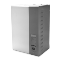
Figure 25: Digital Transducers
Humidifier Terminal Strip
Air Provin
Switch
Duct High Limit
1509857 - 2-10V Duct
Humidity Transducer
Humidity Control
1509858 - 2-10V Wall
Humidity Transducer
Note: 1
.
2
3
4
Install On/Off controls or jumper between
terminal 1 and 2 of humidifier
Terminal 1 is 24 VAC Hot, turn unit off to
avoid shorting while wiring.
Duct High limit can be duct humidity
transducer as shown or duct On/Off humidistat.
Humidity Control can be wall humidity
transducer as shown, duct humidity transducer,
or On/Off humidistat.