Copyright © 2015 Nortek Security & Control LLC 1
2GIG-DW10-345
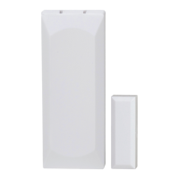
THIN DOOR/WINDOW CONTACT
INSTALLATION INSTRUCTIONS
TheThinDoor/WindowContact(2GIG‐DW10‐345)isdesignedforuse
ondoors,windows,andotherobjectsthatopenandclose.It
communicateswiththecontrolpanelusingthe345MHzfrequency.
Whenthemagnet(whichismountednearthesensor)movesaway
fromorclosertothedoorcontact’ssensor,signalsar
etransmittedto
thecontrolpanel.Thedoorcontactalsohasanexternalinputthat
acceptsconnectionsfromNormally‐Closed(NC)drycontactdevices.
Foraddedprotection,itisalsoequippedwithacovertamper.
Figure 1 ThinDoor/WindowContact—SensorandMagnet
Box Contents
Verifythatthepackageincludesthefollowing:
•1—ThinD
oor/WindowContact
•1—RareEa
rthMagnet
• 2—PhillipsHe
adScrews
• 2—LithiumCoi
nBatteries
•2—AdhesiveFo
amTape
•1—12in(3
0cm)WireLead
Testing the Thin Door/Window Contact
Beforemountingthedoorcontactatthedesiredlocation,performa
walktesttoverifythatitcanestablishgoodRadioFrequency(RF)
communicationswiththecontr olpanel.
NOTE: TofullytesttheThinDoor/WindowContact,seethe
controlpanel’ sInstallationandProgrammingGuide.
Mounting Guidelines
Usetheseguidelineswheninstallingthedoorcontactforinternal
switchusage:
• MountSensor
swithin100ft(30m)oftheControlPanel.
Althoughthetransmittermayhavearangeof350ft(106.7m)
openair,thesensorlocationcanhaveasignificanteffecton
range.Inopen/unobstructedsituations,thetransmitterrange
maybegreater.Inadversewirelessconditions,changingthe
se
nsororientationmayleadtoimprovedrange.
• MountSensor
satLeast4.7in(12cm)AbovetheFloor.
Placingsensorsslightlyabovefloorlevelhelpstominimize
possiblesensordamage.
• Sin
glevs.DoubleDoorInstallation.Forsingle‐door
installation,mountthesensoronthedoorframeandthe
magnetonthedoor.Fordouble‐doorinstallation,mountthe
sensorontheleast‐useddoorandthemagnetonthemost‐
useddoor.
• DoNo
tExposeSensorstoMoistureorExtremeTemperature.
Itisbesttomountsensorsinadrylocationwherethe
operatingtemperaturedonotexceed32°to120°F(0°to49°
C).
• Ke
epSensorsandMagnetsAwayfromMetal/Metallic
Surfaces.Tokeepsensorsandmagnetsawayfrommetalor
metallicsurfaces(forexample,foilwallpaper),itis
recommendedthatyouusespacers(notincluded).Youshould
alsoavoidmountingsensorsinareaswherethereisalarge
quantityofmetalorelectricalwi
ring(forexample,neara
furnaceorinautilityroom).
• AlignMa
gnetwithSensor.Makesurethealignmentarrowon
themagnetpointstothecenteralignmentmarkonthesensor
(seeFigure1ThinDoor/
WindowContact—Sensorand
Magnet).
Mounting the Thin Door/Window Contact
Usethefigurebelowasaguidelinewhenmountingthedoorcontact.
Instep7below,youhavetheoptiontomountthedoorcontactwith
anexternalinputwireforanNCdrycontactdevice.
Figure 2 ThinDoor/WindowContact—BackplateandBatteryCompartment
Tomountthedoorcontact:
1 Atthetopofthesensor,pressdownonthecliptounlockthe
sensor’sbackplate.Then,gentlypulldownonthebackplateto
removeit.
2 Onthebackplate,drill‐throughtopandbottommountingholesif
needed(seeFigure2ThinDoor/WindowContact—Backplateand
BatteryCompartment).
3 Holdingthebackplatelocation,placethebottommountinghole
asfollows:
• SingleDoorIns
tallation.Atthedesiredlocationonthedoor
frame.
• DoubleDoorIns
tallation.Atthedesiredlocationontheleast‐
useddoor.
A ThinDoor/WindowContactSensor
B ThinDoor/WindowContactMagnet
C AlignmentMarksonSensor
D AlignmentArrowonMagnet
A Accessholeforexternalinputwire(onbackplate)
B Topandbottommountingholes(onbackplate)
C Externalinputwirejack(onsensor)
D Tamperswitch(onsensor)
E 3‐Volt(3V)lithiumcoinbatterycompartments(onsensor)
F Metalclipsforremovingbatteries(onsensor)