24
Air Handler with Fixed Speed High Efficiency Motor
10436940
07/22
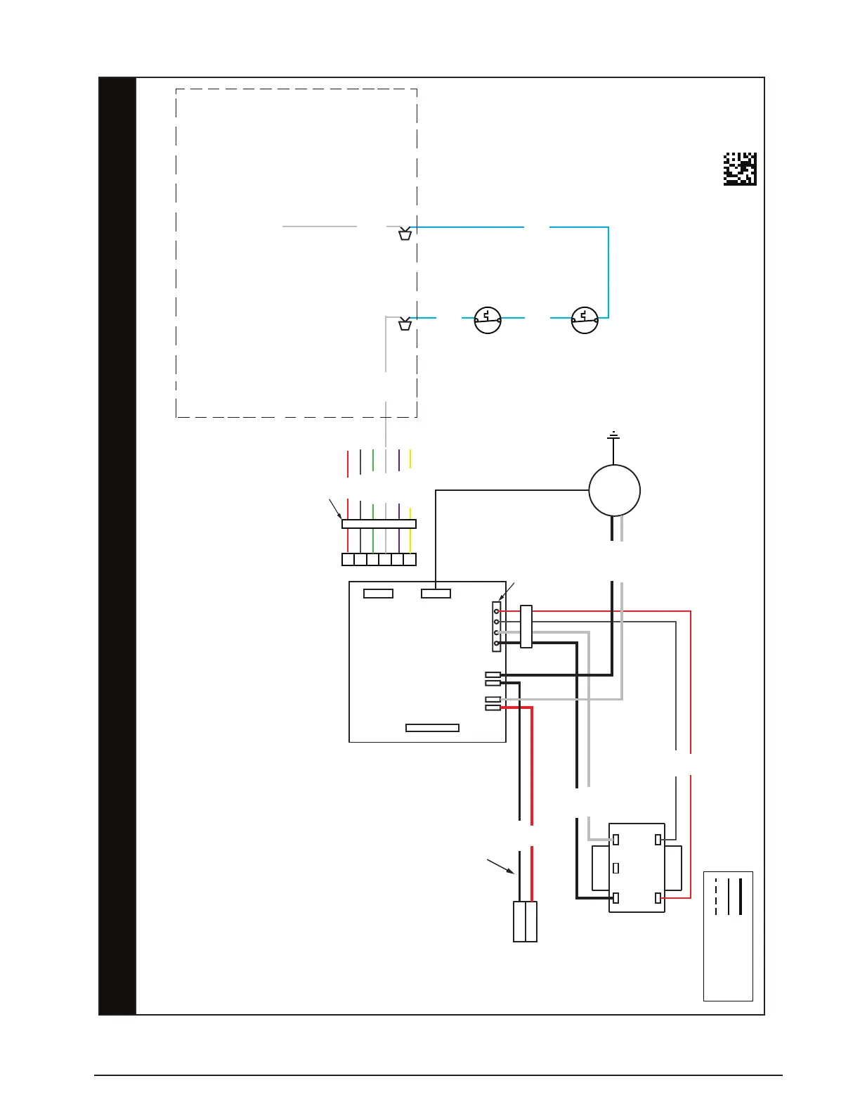
FIELD WIRING
LEGEND:
LOW VOLTAGE
HIGH VOLTAGE
NOTES:
1. The blower motor speed tap connection may not be
as shown. See the Installation Instructions.
2. Disconnect all power before servicing.
3. Transformer may have a dual voltage
primary tap. Match the tap position with the supply
voltage used.
4. If the internal wiring is replaced,use only 105°C
copper wire of the same gauge.
Remarques
1. Le connecteur de vitesse du moteur du ventilateur
peut différer de l’illustration. Consultez les
Instructions d’installation.
2. Débranchez toutes les sources d’alimentation
avant l’entretien.
3. Le transformateur peut avoir un robinet principal à
double tension. Agencez la position du robinet au
type de tension de l’installation.
4. Si le câblage interne est remplacé, utilisez
seulement un fil de cuivre 105° C du même gabarit.
WIRING DIAGRAM
R
C
G
W
D
Y
6-PIN PLUG
1
2
240
24 V
208 COM
TRANSFORMER
R
C
HEATER PLUG
MOTOR
L1
L2
RL1 L2 C
4-PIN PLUG
MOTOR
HARNESS
BLOWER
LIMIT
BLOWER
LIMIT
BLACK
WHITE
BLACK
RED
BLACK
WHITE
RED
GRAY
RED
GREEN
GRAY
WHITE
YELLOW
VIOLET
CONNECT TO W ON CONTROL
BOARD ONLY WHEN ELECTRIC
HEATER KIT IS INSTALLED
CONNECT TO WHITE WIRE
ON HEATER KIT ONLY WHEN
ELECTRIC HEATER KIT
IS INSTALLED
WHITE WIRE FROM
ELECTRIC HEATER KIT
ACCESSORY
BLUE
BLUE
BLUE
WHITE
WHITE
CUT WIRES TO REMOVE PLUG HOUSING
WHEN HEATER KIT NOT INSTALLED
Figure 16. B64EM Wiring Diagram
 Loading...