Do you have a question about the Nortek B5BM Series and is the answer not in the manual?
Highlights critical safety warnings for electrical shock, fire, explosion, and potential hazards during installation and servicing.
Emphasizes adherence to local codes, regulations, and safety standards for installation and servicing.
Provides essential details before unit installation, including inspection, load calculation, and electrical checks.
Guidelines for operating the air handler during construction to prevent damage and maintain performance.
Guidance on selecting the optimal job site location considering power, service access, and noise levels.
Details minimum clearances required around the unit for proper installation and servicing.
Specific guidelines for installing the air handler in a residential garage, including safety precautions.
Guidelines for installing plenums and air ducts according to NFPA standards and local codes.
Information on the need for and selection of air filters for the unit.
Guidance on using acoustical lining or fiber duct work for noise reduction.
Instructions for carefully removing the unit from its shipping crate and inspecting for damage.
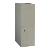
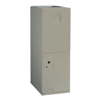
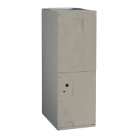
Details on applying the air handler in upflow, downflow, or horizontal mounting configurations.
Specific instructions for installing the unit in an upflow configuration.
Instructions for installing the unit in a downflow configuration using an accessory kit.
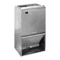
Guidance for installing the unit horizontally in attics, basements, or crawl spaces.
Step-by-step instructions for performing horizontal right discharge installations.
Step-by-step instructions for performing horizontal left discharge installations.
Instructions for removing and installing the correct orifice size for refrigerant line connections.
Steps for connecting refrigerant linesets, including important notes for TXV valve installations.
Details on ensuring proper condensate drainage, including trap installation and auxiliary pan requirements.
A pre-installation check to verify voltage, wiring diagrams, and secure connections before electrical hookup.
Guidelines for connecting line voltage power supply, including disconnect requirements and circuit protection.
Instructions for proper unit grounding to minimize personal injury risk during electrical faults.
Procedures for connecting low voltage wiring to the thermostat and the unit's terminal block.
Explains the function of the control board and its timing sequences for blower and heating/cooling.
Instructions on how to install electric heater kits, including wiring connections.
Pre-startup inspections including unit level, clearances, duct connections, and filter installation.
Procedures for checking and adjusting the system refrigerant charge using service ports.
Instructions for testing blower operation in continuous and auto modes for airflow verification.
Steps to test the unit's cooling operation, verifying air temperature and blower cycles.
Steps to test the unit's heating operation, verifying air temperature and blower cycles.
Guidance on determining nominal system capacity and adjusting blower speed settings for optimal performance.
Recommendations for monthly cleaning or replacement of air filters for optimal performance.
Instructions for cleaning dirt and lint from the blower compartment to prevent overheating.
Guidance on inspecting blower wheel blades for dirt accumulation and cleaning as needed.
Recommendations for inspecting the blower assembly and motor mounting for tightness and corrosion.
A checklist to diagnose common operational failures, such as power, thermostat, doors, or filter issues.
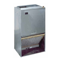
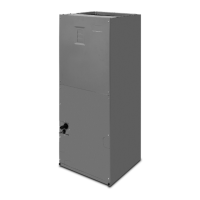
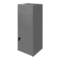
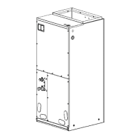
Displays physical dimensions and cabinet sizes of the B5 Series Air Handler.
Provides airflow performance data for different unit configurations and external static pressures.
Diagrams illustrating various thermostat wiring configurations for different system types.
Detailed wiring diagram for variable speed air handlers, including motor settings and delay configurations.
Wiring diagram specific to B5BM Series Air Handlers equipped with an X-13 motor.
Wiring diagram for units with factory-installed electric heat packages.
Tables providing electrical data for circuit ampacity and maximum overcurrent protection based on unit size and heat.
A comprehensive checklist for installers to ensure correct electrical and venting system setup before operation.
| Type | Air Handler |
|---|---|
| Motor Type | PSC or ECM |
| Airflow Range | 2000 CFM |
| Static Pressure Range | Up to 1.0 in. w.g. |
| Power Supply | 208/230V, 1 Phase |
| Cabinet Construction | Galvanized Steel |
| Coil Type | Aluminum |