9
Connecting the Linesets
IMPORTANT NOTES FOR HORIZONTAL OR
DOWNFLOWINSTALLATIONSWITHTXVVALVE:
• The sensing bulb must be located flush against the
suction line for optimum heat transfer.
• Avoid attaching the sensing bulb to the lowest part of
the suction line where condensate may accumulate.
• Do not locate the sensing bulb on vertical sections
of the lineset.
• For horizontal lines, the bulb should not be located
at 12 or 6 o’clock position of the suction line. The
best location is at 4 or 8 o’clock.
• For additional information on proper sensing bulb
locations, please refer to the valve manufacturer’s
instructions.
IMPORTANT: The Orifice Removal & Installation steps
on page 8 must be performed before the linesets are
connected.
1. Remove grommets from line set holes.
CAUTION:
It is recommended that a wet rag be wrapped
around the suction line in front of the close
off plate or the sensing bulb (if TXV is
installed) before applying heat. Failure to keep
components cool during brazing may result
in structural damage, premature equipment
failure, or possible personal injury.
2. Remove the rubber plug on the suction line.
3. Route and cut both lineset tubes to proper length in
accordance with the outdoor unit specifications. Verify
the ends are round, clean, and free of any burrs.
4. Position grommet on line set with sufficient distance away
from brazing area. Brazing processes can permanently
damage grommets.
5. Connect the suction and liquid lineset tubes.
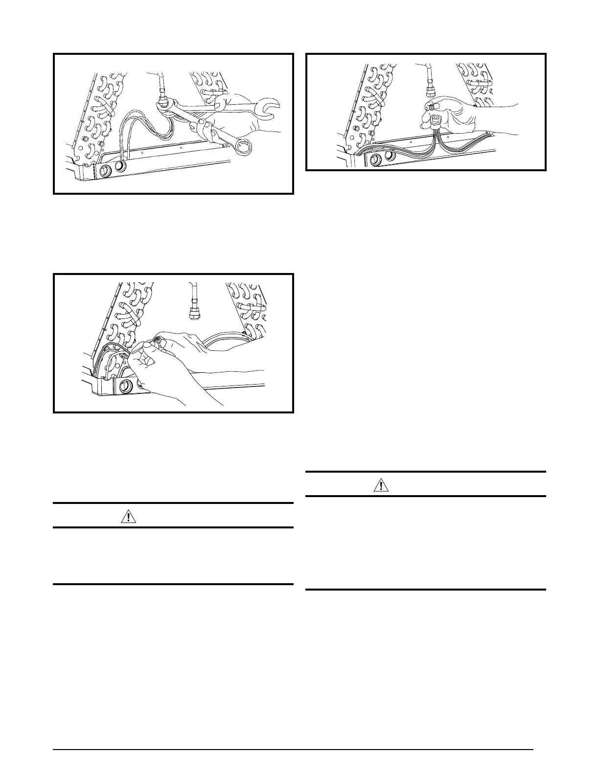
Figure 8. Restrictor Insertion into Distributor Body
6. Insert a light-gauge wire hook between the distributor
body and the restrictor orifice while being careful not
to scratch either part. Carefully remove the restrictor
orifice from the distributor body. See Figure 7.
Figure 6. Loosening of Nut & Distributor Body
Figure 7. Removal of Orifice
7. Check the actual size of the new orifice. NOTE: The
size is stamped on its side. Do not use pin gauges to
measure the orifice diameter.
8. Insert the new orifice into the distributor body, rounded
end down. See Figure 8.
CAUTION:
To prevent damage to the unit or internal
components, it is recommended that two
wrenches be used when loosening or tightening
nuts. Do not over tighten!
9. Realign the assembly nut on the distributor body and
hand tighten both components. Mark a line on both
bodies and then tighten an additional 1/4 turn using two
wrenches. The movement of the two lines will show how
much the nut is tightened. If a torque wrench is used,
tighten to 10-12 ft. lbs. or 14-16 Nm.
 Loading...