Do you have a question about the Nortek B64EM Series and is the answer not in the manual?
Pre-installation inspection, damage checks, and system load calculations.
Guidance on selecting the optimal placement for the unit considering access and noise.
Specifies required distances around the unit for easy access and service.
Specific safety instructions for installing the unit in a residential garage.
Guidelines for installing air plenums and ductwork according to standards.
Instructions for safely removing the unit from its shipping carton and crate.
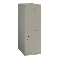
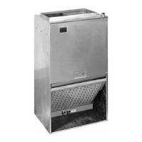
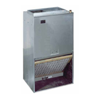
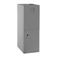
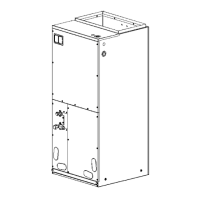
Overview of different mounting configurations available for the air handler.
Details and procedures for installing the unit in an upflow airflow configuration.
Details and procedures for installing the unit in a downflow airflow configuration.
Guidance for installing the unit in various horizontal orientations.
Specific steps for performing a horizontal left-side installation.
Specific steps for performing a horizontal right-side installation.
Instructions for installing the circuit breaker cover, especially for heater kits.
Information about the functions and operations of the control board.
Instructions for connecting two air handlers together for a dual-unit system.
Guidance on purchasing and installing electric heater kits for the unit.
Details on powering a humidifier from the unit's output.
How to configure the unit to enhance humidity removal during cooling.
Instructions for connecting an electronic air cleaner to the unit.
Essential pre-startup checks and inspections before operating the unit.
How to manage airflow for optimal system performance and comfort.
Setting the blower to operate continuously, independent of the thermostat's call.
Configuring the blower for continuous low-speed fan operation.
Instructions on how to properly turn off the blower.
Steps for verifying the unit's proper operation in cooling mode.
Steps for verifying the unit's proper operation in heating mode.
Setting the minimum airflow rate when electric heat is used.
Setting airflow rates for cooling and heat pump operation with variable/fixed speed motors.
How to determine the nominal system capacity for airflow selection.
Configuration details for high-efficiency variable and fixed-speed blower motors.
Setting airflow rates for heating with variable and fixed-speed motors.
Information on air filter types, sizes, and replacement recommendations.
Instructions for cleaning dirt and lint from the blower compartment.
How to inspect and clean the blower fan wheel for optimal operation.
Guidance on inspecting the blower motor and its mounting brackets.
Diagram illustrating the physical dimensions and key features of the B64 series.
An exploded view identifying the various components of the air handler.
Table providing airflow data for B64EM (FSHE) models under various conditions.
Table listing recommended cooling airflow settings based on cabinet size and tonnage.
Table providing airflow data for B64VM (VSHE) models under various conditions.
Details the control board's actions based on signals and operating modes.
Continuation of control board operation details for various system configurations.
Diagrams illustrating common thermostat wiring configurations for different systems.
Wiring diagram for connecting two air handlers together (twinning).
Schematic diagram of the single-stage control board.
Schematic diagram of the two-stage control board.
Diagram of the control board for fixed-speed ECM blower motors.
Diagram of the control board for variable-speed ECM blower motors.
Specific wiring diagram for the B64EM model with fixed speed motor.
Specific wiring diagram for the B64VM model with variable speed motor.
| Brand | Nortek |
|---|---|
| Model | B64EM Series |
| Category | Air Handlers |
| Language | English |