7
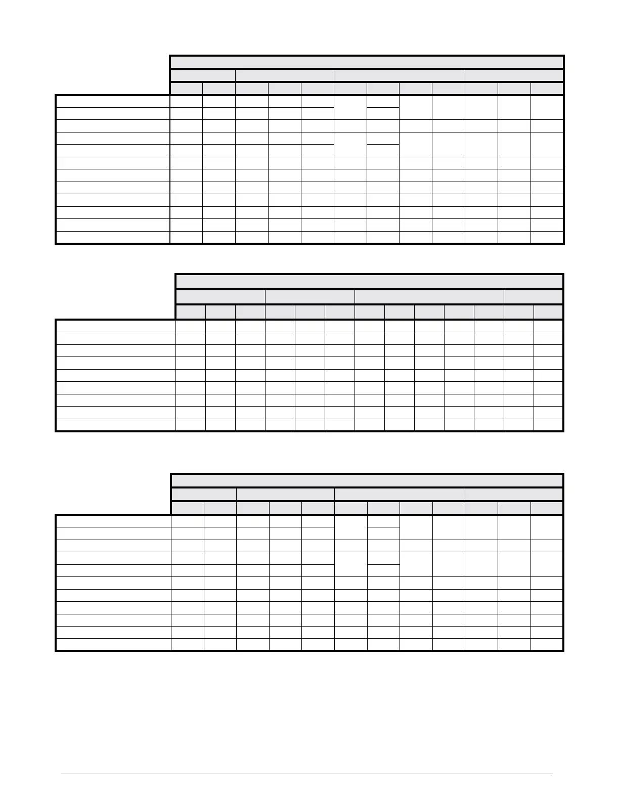
UPFLOW & DOWNFLOW UNITS
A-CABINETS B-CABINETS C-CABINETS D-CABINETS
01824A 03036A 01824B 03036B 03642B 030C 03648C 048C 060C 042D 048D 060D
NomiNal CapaCity, miN BtUH 18,000 30,000 18,000 30,000 36,000
30,000
36,000
48,000 60,000 42,000 48,000 60,000
NomiNal CapaCity, max BtUH 24,000 36,000 24,000 36,000 42,000 48,000
iNstalled orifiCe size (iN.) .048 .061 .055 .067 .071 .061 .067 .077 .083 .071 .077 .083
NomiNal airflow, miN (Cfm) 800 1,000 800 1,000 1,200
1,000
1,200
1,600 2,000 1,400 1,600 2,000
NomiNal airflow, max (Cfm) 800 1,000 800 1,200 1,400 1,600
w - widtH (iN.) 14 1/2 14 1/2 17 1/2 17 1/2 17 1/2 21 21 21 21 24 1/2 24 1/2 24 1/2
H - HeigHt (iN.) 20 3/4 20 3/4 20 3/4 20 3/4 26 3/4 26 3/4 26 3/4 30 1/4 30 1/4 30 1/4 30 1/4 30 1/4
Hl - HeigHt of liqUid liNe (iN.) 17 1/2 17 1/2 17 1/2 17 1/2 23 1/2 23 1/2 23 1/2 27 27 27 27 27
Hs - HeigHt of sUCtioN liNe (iN.) 15 1/2 15 1/2 15 1/2 15 1/2 21 1/2 21 1/2 21 1/2 25 25 25 25 25
CoNNeCtioN - liqUid liNe 3/8 3/8 3/8 3/8 3/8 3/8 3/8 3/8 3/8 3/8 3/8 3/8
CoNNeCtioN - sUCtioN liNe 3/4 3/4 3/4 3/4 7/8 3/4 7/8 7/8 7/8 7/8 7/8 7/8
HorizoNtal draiN Kit (5) 920265 920265 920265 920265 920266 920266 920266 920267 920267 920267 920267 920267
Table 3. C7BA Coil Specifications (Orifice Only)
HORIZONTAL UNITS
A-CABINETS B-CABINETS C-CABINETS D-CABINETS
01824A 03036A 01824B 03036B 03642B 030C 03648C 048C 060C 042D 048D 060D
NomiNal CapaCity, miN BtUH 18,000 30,000 18,000 30,000 36,000
30,000
36,000
48,000 60,000 42,000 48,000 60,000
NomiNal CapaCity, max BtUH 24,000 36,000 24,000 36,000 42,000 48,000
iNstalled orifiCe size (iN.) .048 .061 .055 .067 .071 .061 .067 .077 .083 .071 .077 .083
NomiNal airflow, miN (Cfm) 800 1,000 800 1,000 1,200
1,000
1,200
1,600 2,000 1,400 1,600 2,000
NomiNal airflow, max (Cfm) 800 1,000 800 1,200 1,400 1,600
w - widtH (iN.) 14 1/2 14 1/2 17 1/2 17 1/2 17 1/2 21 21 21 21 24 1/2 24 1/2 24 1/2
H - HeigHt (iN.) 26 3/4 26 3/4 26 3/4 26 3/4 26 3/4 26 3/4 26 3/4 30 1/4 30 1/4 30 1/4 30 1/4 30 1/4
Hl - HeigHt of liqUid liNe (iN.) 23 1/2 23 1/2 23 1/2 23 1/2 23 1/2 23 1/2 23 1/2 27 27 27 27 27
Hs - HeigHt of sUCtioN liNe (iN.) 21 1/2 21 1/2 21 1/2 21 1/2 21 1/2 21 1/2 21 1/2 25 25 25 25 25
CoNNeCtioN - liqUid liNe 3/8 3/8 3/8 3/8 3/8 3/8 3/8 3/8 3/8 3/8 3/8 3/8
CoNNeCtioN - sUCtioN liNe 3/4 3/4 3/4 3/4 7/8 3/4 7/8 7/8 7/8 7/8 7/8 7/8
Table 4. C7BH Coil Specifications (TXV Only)
HORIZONTAL UNITS (3)
A-CABINETS B-CABINETS C-CABINETS D-CABINETS
X24C-A X30C-A X36C-A X24C-B X30C-B X36C-B X30C-C X36C-C X42C-C X48C-C X60C-C X48C-D X60C-D
NomiNal CapaCity, BtUH 24,000 30,000 36,000 24,000 30,000 36,000 30,000 36,000 42,000 48,000 60,000 48,000 60,000
meteriNg deviCe TXV TXV TXV TXV TXV TXV TXV TXV TXV TXV TXV TXV TXV
NomiNal airflow, (Cfm) 800 1000 1000 800 1000 1200 1000 1200 1400 1600 2000 1600 2000
w - widtH (iN.) 14.5 14.5 14.5 17.5 17.5 17.5 21 21 21 21 21 24.5 24.5
H - HeigHt (iN.) 20.75 20.75 20.75 20.75 20.75 20.75 26.75 26.75 26.75 26.75 30.25 30.25 30.25
Hl - HeigHt of liqUid liNe (iN.) 17.5 17.5 17.5 17.5 17.5 17.5 23.5 23.5 23.5 23.5 27 27 27
Hs - HeigHt of sUCtioN liNe (iN.) 15.5 15.5 15.5 15.5 15.5 15.5 21.5 21.5 21.5 21.5 25 25 25
CoNNeCtioN - liqUid liNe 3/8 3/8 3/8 3/8 3/8 3/8 3/8 3/8 3/8 3/8 3/8 3/8 3/8
CoNNeCtioN - sUCtioN liNe 3/4 3/4 3/4 3/4 3/4 3/4 3/4 7/8 7/8 7/8 7/8 7/8 7/8
Table 5. C7BH Coil Specifications (Orifice)
NOTES:
1. Individual restrictors are available by part number - PN664*** (where *** represents the size). Example: 664103 is a restrictor 0.103 in diameter.
2. Refer to sales specification sheets for Listed/Certified combinations of equipment and required accessories.
3. X in the model description designates factory installed TXV for R-410a refrigerant.
4. Refer to the current AHRI Directory for certified ratings of split systems.
5. Not required for “H” horizontal ready coils.