61
BMC II AMAT Quick Reference Guide
PCA Switch and Strap Settings
Note 1: Pin 1 is designated by a white dot on all of the PCAs. These
tables list the factory default settings.
Note 2: Some of the PCAs listed in this section are no longer being
manufactured. These PCAs are identified by an (MD) following the
PCA’s Product Equipment Code.
Table 7
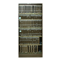
NT6M62xx CPU PCA
Switch # Position
S2 1 OFF
2 OFF
3 ON
4 OFF
Jumpers Pin
J3 1-2
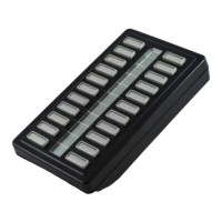
Table 8
CPU LED display codes
LED Alarm level Notes
BLANK N/A Power failure
U. N/A Busak faulty
P. N/A Wait faulty
H. N/A Processor failed - halt
r. N/A Processor reset - initial start-up
L. N/A Clock faulty (also indicated by lack of
decimal point)
E. N/A Invalid CPU response (also displayed
whenever switch 3 on SW2 is in the OFF
position
d. Critical Level 3 Processor switch occurs
c. Critical Level 2 Processor switch occurs
b. Critical Level 1 Processor switch occurs
A. Critical Level 0 Alarm only, no processor switch
9. Major Level 3 Processor switch occurs
8. Major Level 2 Processor switch occurs

 Loading...