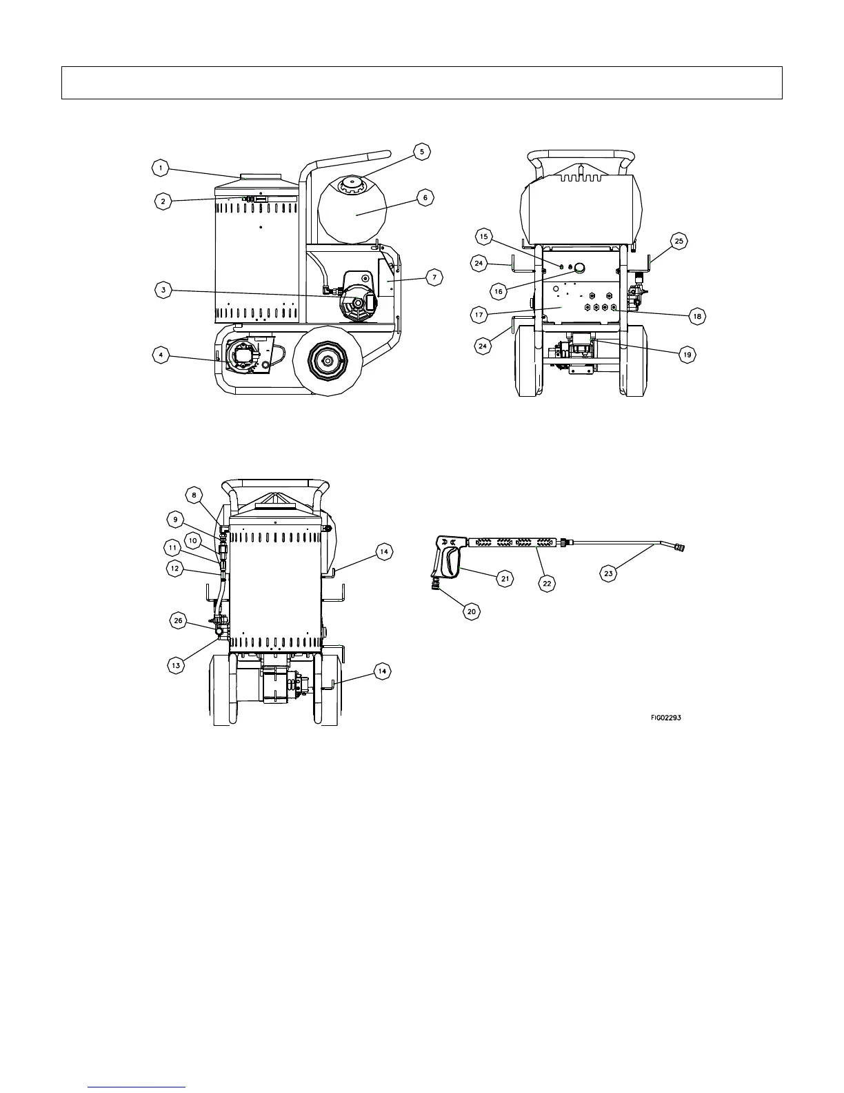
Component Identification
1. Exhaust Vent: Provides an exit for burner exhaust
gases.
2. High Pressure Water Outlet: A passage for water
to exit pump and enter the hose.
3. Motor: Electric motor powers the pump.
4. Burner: The oil burner is preset and performance
tested at the factory. The Burner may need initial
adjustment for peak performance. See “Oil Burner
Adjustment” section for instructions on initial
adjustment of the oil burner. You will need to use
the handle to tip the pressure washer up in order to
access the Burner from underneath.
5. Fuel Fill Cap: Vented cover for fuel tank.
6. Fuel Tank: The Burner has a 8.25 gal. fuel tank-
kerosene, #1 or #2 diesel, or fuel oil may be used.
Do not mix fuel types.
7. Control Box: Flat surface for mounting switches.
8. Elbow: Junction between Swivel Fitting (Reference
9) and coil inlet.
9. Swivel Fitting: Connection point of Flow Switch
(Reference 10) to Elbow (Reference 8).
10. Flow Switch: Water activated switch to control on
and off of burner.
11. Tee: Junction between Safety Relief Valve
(Reference 12) and Flow Switch (Reference 10).
12. Safety Relief Valve: Controls over pressure (Pop
Off Valve).
Machine Component Identification
157305, 157306, 157307, 157308
Ref # Description Ref # Description Ref # Description
1 Exhaust Vent 10 Flow Switch 19 Fuel Filter
2 High Pressure Water Outlet 11 Tee 20 Quick Connector
3 Motor 12 Safety Relief Valve 21 Spray Gun
4 Burner 13 Pump 22 Grip
5 Fuel Fill Cap 14 Gun Hooks 23 Lance Wand
6 Fuel Tank 15 Power Switch 24 Power Cord Hangers
7 Control Box 16 Thermostat 25 High Pressure Hose Hanger
8 Elbow 17 Service Panel 26 Garden Hose Water Inlet
9 Swivel Fitting 18 Nozzles
 Loading...