26
Oil Burner Adjustment (only needed if white exhaust smoke appears)
The oil burner is preset and performance tested at
factory elevation of 1100 feet. Different altitudes may
require a one-time initial burner adjustment.
CAUTION: Improper fuel-air mixture
If white smoke appears from the burner exhaust vent
during start-up or operation, discontinue use and
readjust air bands.
Adjusting burner will require accessing it from
underneath the pressure washer while someone else is
operating the spray gun.
1. Make sure burner has cooled before attempting to
adjust.
2. Use handle to tip pressure washer forward so
front edge of burner fuel tank is resting on the
ground. Prop rear axle up in this position with two
16” jack stands.
WARNING: Crushing hazard
The burner adjustment procedure requires part of an
individual’s body to be underneath the pressure washer
while it is elevated. Always ensure the pressure washer
is elevated and securely blocked before working on the
burner underneath.
3. Begin operation of pressure washer and switch
on burner, as instructed in “Operation” section.
Have someone operate spray gun so burner fires.
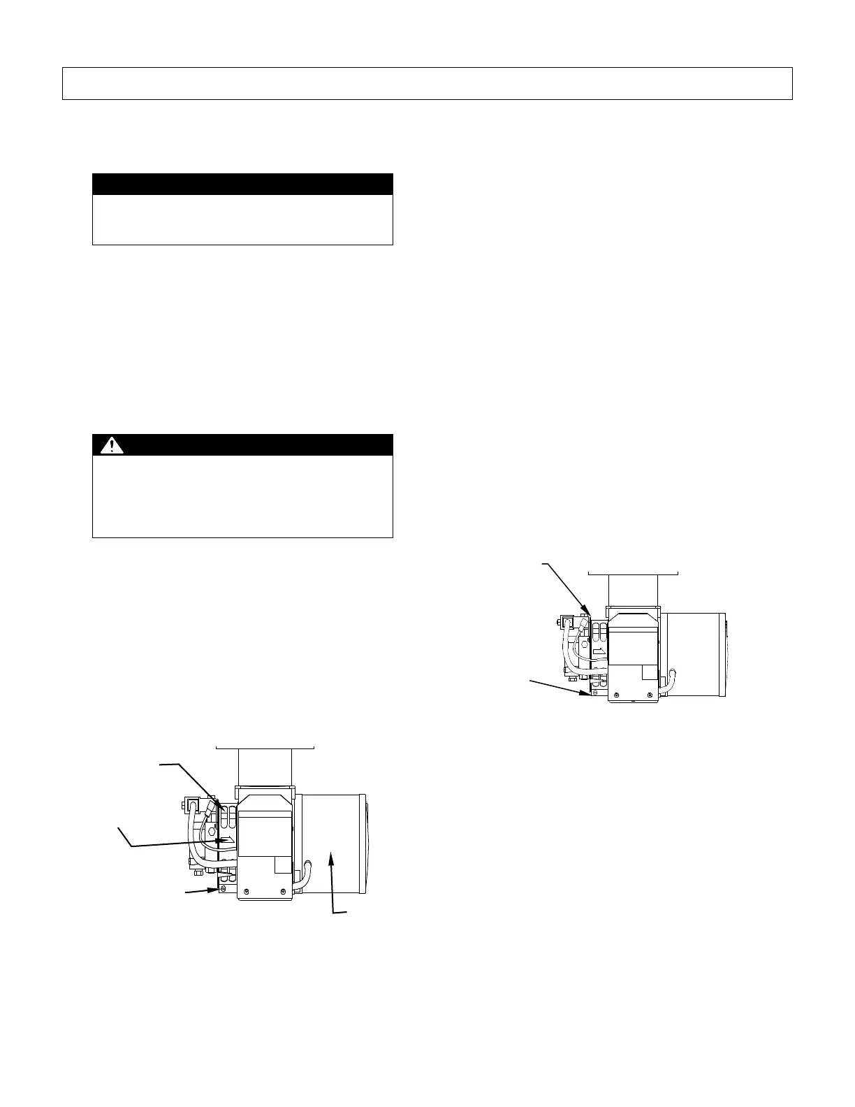
4. Locate air intake adjustment band as shown in
Figure 24 below. Clear if necessary to see
numbers. Observe position of arrow on air band
relative to calibration numbers directly to the right.
(Factory calibration starts out at close to “1”)
Figure 24
5. Loosen locking screw and rotate air band closed
until black smoke appears from burner exhaust
vent. Note which number arrow points to.
6. Slowly open air band until white smoke just starts
to appear.
7. Turn air band halfway back to black smoke
position previously noted. Tighten locking screw.
8. Now fine-tune burner air by adjusting shutter:
a. Locate shutter as shown in Figure 25 below.
Shutter is a thin circular metal plate located on
outside of air band. It adjusts independently
from air band and is used to fine-tune the
amount of intake air.
b. Observe the aluminum pointer attached to the
shutter. It points to the same set of calibration
numbers as air band arrow. Observe which
number it points to at start of this adjustment
step.
c. Loosen shutter lock screw. Turn shutter using
the aluminum pointer until exhaust is cleanest.
Tighten shutter lock screw.
Figure 25 – Shutter Adjustment
 Loading...