Do you have a question about the Northern Lights M673L3G and is the answer not in the manual?
Identifies the models covered by the manual and provides model number details.
Explains the structure of model numbers and their components.
Details the location and importance of serial numbers for identification.
Information about the warranty registration and its coverage.
General safety instructions and warnings for operating the equipment.
Explains how to interpret safety symbols and signal words used in the manual.
Warnings and procedures to prevent unintended engine starts.
Safety guidelines for handling diesel fuel to prevent fires.
Recommendations for appropriate protective clothing and hearing protection.
Guidelines for performing maintenance safely.
Warnings about entanglement hazards with rotating parts.
Importance of safety guards and precautions for handling batteries.
Safety guidelines for chemicals, ventilation, and paint heating.
Safety procedures for cooling systems and high-pressure fluids.
Precautions against heating near pressurized fluid lines due to flammability.
Warnings for high-pressure fuel systems and hot exhaust.
Safety measures for asbestos, lifting, tools, and waste disposal.
Policy for avoiding hazardous situations during maintenance.
Procedures for safely locking out electrical equipment during maintenance.
Procedures for locking out pneumatic and hydraulic equipment.
Ensuring stored energy is relieved and isolation is verified before work.
Procedures for safely restoring energy after maintenance.
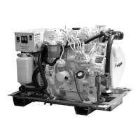
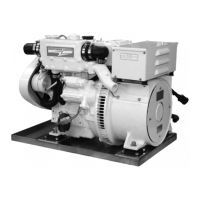
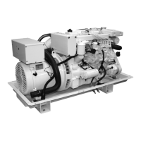
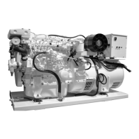
Identifies components on the service side of the generator.
Identifies components on the non-service side of the generator.
Identifies service side components for specific serial number ranges.
Details the components and functions of the Series 1-B control panel.
Details the components and functions of the Series 3 generator control panel.
Details the components and functions of the Series 4 generator control panel.
Guidelines for the initial break-in period of a new engine.
Pre-start checks and procedures before operating the generator.
Step-by-step instructions for starting the engine.
Procedures for monitoring and operating the generator during use.
Procedures for safely shutting down the generator.
Explains shutdown systems, alarms, and troubleshooting steps for them.
Lists recommended spare parts for field service and kits.
Outlines required maintenance tasks based on daily, 50, 100, 200, 500, 1000, and 2500 hour intervals.
Procedure for checking the engine oil level using the dipstick.
Instructions for changing the engine oil and filter.
Steps for replacing the engine's lube oil filter.
Instructions for inspecting and cleaning the air cleaner element.
Procedure for checking the tension and wear of V-belts.
Steps for adjusting valve clearances on the engine.
Guidelines for using clean, high-quality diesel fuels and proper storage.
Procedure for checking and changing primary and secondary fuel filters.
General information and safety precautions for the cooling system.
Procedure for checking the engine coolant level.
Instructions for flushing and refilling the cooling system.
Procedures for servicing and replacing fuel injectors.
Guidelines for checking and servicing the fuel injection pump.
Maintenance for heat exchanger, raw water pump, and exhaust elbow.
Maintenance for generator ends and general electrical system information.
Information on checking and testing glow plugs.
Safety and procedures for booster batteries and general battery care.
Preparation steps for storing the generator set for extended periods.
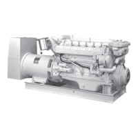
Overview of the AC generator and its function.
Identifies generator components and control box elements.
Instructions for connecting the generator for different voltage outputs.
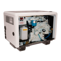
Guidelines for operating, environmental considerations, and ventilation.
General maintenance procedures, voltage adjustment, bearing, and brush checks.
Step-by-step instructions for replacing generator brushes.
Information on generator and AVR protection mechanisms.
Troubleshooting common problems with the DC electrical system, starter, and battery.
Steps to troubleshoot when the entire electrical system fails.
Diagnosing and resolving engine starting, running, and power issues.
Troubleshooting engine overheating, knocks, and low temperature issues.
Identifying reasons for high fuel consumption.
Causes and solutions for low oil pressure and high oil consumption.
Diagnosing causes of black, gray, or white smoke from the engine exhaust.
Step-by-step instructions for bleeding air from the fuel system.
General specifications for the generator models.
Cooling system specifications for the generator models.
Wiring diagram for the S-1 control panel with B+ Deutsch connection.
Wiring diagram for the S-1B control panel with B+ connection.
Wiring diagram for S-3B/S-3C panels with Viewline B+ connection.
AC wiring diagram for dual voltage operation.
AC wiring diagram for 200-240 VAC operation.
AC wiring diagram for 120 VAC operation.
DC wiring diagram for 12 VDC standard ground B+ control.
DC wiring diagram for 12 VDC isolated ground B+ control.
DC wiring diagram for 12 VDC standard ground B+ control.
DC wiring diagram for 12 VDC isolated ground B+ control.
| Brand | Northern Lights |
|---|---|
| Model | M673L3G |
| Category | Portable Generator |
| Language | English |