Do you have a question about the Northern Lights M673L3 and is the answer not in the manual?
Identify generator set models and serial numbers.
Explains model number structure and meaning for identification.
Locating and using serial numbers for service and parts.
Crucial safety guidelines before installation and operation.
Understanding signal words and symbols for hazard identification.
Precautions for handling diesel fuel to prevent fires and explosions.
Safety procedures for servicing, including protective clothing.
Warnings about rotating parts, guards, and battery handling.
Safety for chemicals, cooling systems, and high-pressure fluids.
Safety for fuel systems, exhaust, and asbestos components.
Guidelines for safe tool usage, lifting, and waste disposal.
General principles for avoiding hazards during servicing operations.
Steps for electrical, pneumatic, and hydraulic lock out/tag out.
Verifying isolation, stored energy, and safe restart procedures.
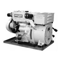
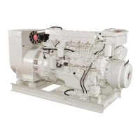
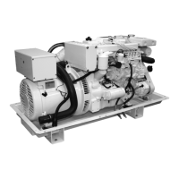
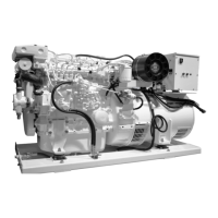
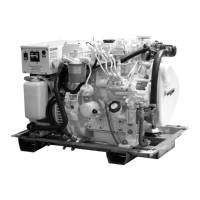
Identifies components on the service side of specific generator models.
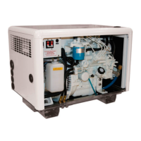
Identifies components on the non-service side of specific generator models.
Details and labels for the Series 1-B generator control panel.
Details and labels for the Series 3 generator control panel.
Details and labels for the Series 4 generator control panel.
Guidelines for the initial engine break-in period for optimal performance.
Essential checks before starting the generator, including fluid levels.
Step-by-step instructions for safely starting the engine.
Procedures and gauge checks for normal generator operation.
Correct procedures for safely shutting down the generator set.
Explains automatic shutdowns and alarm conditions for engine protection.
Lists recommended spare parts for field service and maintenance.
Procedures for checking, changing oil, and replacing the oil filter.
Maintenance for air cleaner, V-belts, and valve clearances.
Fuel specifications, filter checks, and replacement procedures.
Cooling system checks, flushing, and coolant specifications.
Procedures for servicing fuel injectors and the injection pump.
Cleaning heat exchangers and changing raw water pump impellers.
General electrical precautions and glow plug testing.
Procedures for battery care, cleaning, and checking.
Preparing the generator for long-term storage or out-of-service periods.
Identification of generator set, generator, and control box components.
Instructions for making electrical connections for various voltage outputs.
Guidelines for generator operation, environment, and key maintenance tasks.
Steps for replacing brushes and information on generator protection.
Common problems and solutions for the DC electrical system.
Troubleshooting engine starting, running irregularly, and power loss.
Diagnosing and resolving engine overheating, knocking, and temperature problems.
Addressing low oil pressure, high oil consumption, and exhaust smoke.
General specifications and dimensions for marine generator models.
Specifications for the cooling system components and capacity.
Identifies components and shows wiring for generator set and connections.
Details generator operation, maintenance, brush replacement, and protection.
Wiring diagram for the 12 VDC DC engine system.
Wiring diagram for the S-1 control panel with B+ connection.
Wiring diagram for the S-1B control panel with B+ connection.
Wiring diagram for S-3B/S-3C panels with Viewline B+.
AC engine wiring for dual voltage outputs and frequencies.
AC engine wiring for 200-240 VAC output.
AC engine wiring for 120 VAC output.
DC engine wiring for standard ground B+ control.
DC engine wiring for isolated ground B+ control.
Specific DC engine wiring for standard ground B+ control.
Specific DC engine wiring for isolated ground B+ control.
| Brand | Northern Lights |
|---|---|
| Model | M673L3 |
| Category | Portable Generator |
| Language | English |