DETECTOR TEST LOG
Detector Identification Information
Manufacturer and Serial Date
Detector Model: __________________ Number: ___________________ Installed: ________________
Description of Detector Location:
_____________________________________________________________________________________
_____________________________________________________________________________________
_____________________________________________________________________________________
Test Results and Maintenance Data
Date Test Test Maintenance
Tested Description Results Performed Comments
_______ __________ _______ ____________ ___________________________
_______ __________ _______ ____________ ___________________________
_______ __________ _______ ____________ ___________________________
_______ __________ _______ ____________ ___________________________
_______ __________ _______ ____________ ___________________________
_______ __________ _______ ____________ ___________________________
_______ __________ _______ ____________ ___________________________
_______ __________ _______ ____________ ___________________________
_______ __________ _______ ____________ ___________________________
_______ __________ _______ ____________ ___________________________
_______ __________ _______ ____________ ___________________________
_______ __________ _______ ____________ ___________________________
_______ __________ _______ ____________ ___________________________
_______ __________ _______ ____________ ___________________________
_______ __________ _______ ____________ ___________________________
_______ __________ _______ ____________ ___________________________
_______ __________ _______ ____________ ___________________________
_______ __________ _______ ____________ ___________________________
DHX-501 INTELLIGENT AIR DUCT SMOKE DETECTOR HOUSING
INSTALLATION AND MAINTENANCE INSTRUCTIONS
Before installing detectors, please thoroughly read the NEMA
Guide for Proper Use of Smoke Detectors in Duct
Applications
, which provides detailed information on detector spacing, placement, zoning, wiring, and special
applications. Copies of this manual are available from NEMA (National Electrical Manufacturers Association, 2101
L Street NW, Washington, DC 20037). NFPA Standards 72 and 90A should also be referenced for detailed
information.
NOTICE: This manual should be left with the owner/user of this equipment.
IMPORTANT: This detector must be tested and maintained regularly following NFPA 72 requirements. The detector
should be cleaned at least once a year.
GENERAL DESCRIPTION
An HVAC system supplies conditioned air to virtually every area of a building. Smoke introduced into this air duct
system will be distributed to the entire building. Smoke detectors designed for use in air duct systems are used to
sense the presence of smoke in the duct.
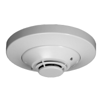
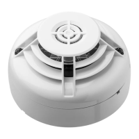
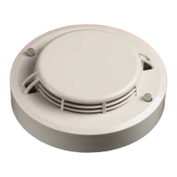
The DHX-501 Air Duct Detector Housings are used with Notifier's Intelligent Model CPX-551 ionization detector heads
and Model SDX-551 photoelectronic detector heads. These two smoke detection methods are combined with an
efficient housing design that samples air passing through a duct and allows early detection of a developing hazardous
condition. When sufficient smoke is sensed, an alarm signal is initiated at the fire control panel monitoring the detector,
and appropriate action can be taken to shut off fans and blowers, change over air handling systems, etc. This can
prevent the distribution of toxic smoke and fire gases throughout the areas served by the duct system.
The DHX-501 operates from a Notifier Signaling Line Circuit (SLC). When external devices are used, separate 120/
240 VAC or 24 VAC/DC is required. Two form-C relay output contacts are available for control purposes. Two LEDs
on each detector latch on to provide a local alarm indication. Remote alarm indication is made possible by utilizing
the 12 volt alarm output. The duct detector can be tested and the alarm can be reset by the control panel. See panel
instructions for details.
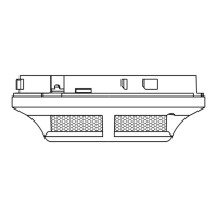
CONTENTS OF THE DUCT DETECTOR HOUSING KIT
The DHX-501 Series Air Duct Detector housings consist of the following items: (See Figure 1.)
See Note 1 on Page 2 for Inlet
Sampling Tube and Detector
Supply information.
N500-03-00 1 I56-456-07
Notifier, 12 Clintonville Rd., Northford , CT 06472-1652 (203) 484-7161