0
1
2
3
4
9
8
7
6
5
0
TENS
ONES
ADDRESS
LOOP
9
8
7
6
5
4
3
2
1
0
9
8
7
6
5
4
3
2
1
10
11
12
13
14
15
ISOLATED
QUADRANT
0
1
2
3
4
9
8
7
6
5
0
TE
N
S
O
N
E
S
A
D
D
R
E
SS
LO
O
P
9
8
7
6
5
4
3
2
1
0
9
8
7
6
5
4
3
2
1
10
11
12
13
14
15
N500-47-00 1 I56-1170-04
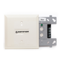
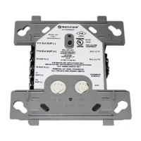
FRM-1 Relay Control Module
INSTALLATION AND MAINTENANCE INSTRUCTIONS
Before Installing
This information is included as a quick reference installation
guide. Refer to the appropriate Notier control panel installation
manual for detailed system information. If the modules will be
installed in an existing operational system, inform the operator
and local authority that the system will be temporarily out of ser-
vice. Disconnect power to the control panel before installing the
modules.
NOTICE: This manual should be left with the owner/user of this
equipment.
General Description
The FRM-1 Relay Control Module is intended for use in intelligent,
two-wire systems where the individual address of each module is
selected using the built-in rotary switches. It allows a compatible
control panel to switch discrete contacts by code command. The
relay contains two isolated sets of Form-C contacts, which operate
as a DPDT switch and are rated in accordance with the table in
the manual. Circuit connections to the relay contacts are not su-
pervised by the module. The module also has a panel controlled
LED indicator. This module can be used to replace a CMX-2 mod-
ule that has been congured for Form-C operation.
Compatibility Requirements
To ensure proper operation, this module shall be connected to a
compatible Notier system control panel (list available from Noti-
er).
Mounting
The FRM-1 mounts directly to 4″ square electrical boxes (see Fig-
ure 2A). The box must have a minimum depth of 2
1
/
8
″. Surface
mounted electrical boxes (SMB500) are available from Notier.
Wiring
NOTE: All wiring must conform to applicable local codes, ordi-
nances, and regulations. When using control modules in
nonpower limited applications, the CB500 Module Bar-
rier must be used to meet UL requirements for the sepa-
ration of power-limited and nonpower-limited terminals
and wiring. The barrier must be inserted into a 4″x4″x2
1
/
8
″ junction box, and the control module must be placed
into the barrier and attached to the junction box (Figure
2A). The power-limited wiring must be placed into the
isolated quadrant of the module barrier (Figure 2B).
1. Install module wiring in accordance with the job drawings and
Figure 1. Removing
rotary switch stop:
Figure 2A. Module mounting with barrier:
A78-2611-11
Figure 2B:
A78-2610-08
A78-2318-07
Specications
Normal Operating Voltage: 15 to 32 VDC
Maximum Current Draw: 6.5 mA (LED on)
Average Operating Current: 270µA (LED ashing)
EOL Resistance: Not used
Temperature Range: 32˚F to 120˚F (0˚C to 49˚C)
Humidity: 10% to 93% Noncondensing
Dimensions: 4
1
/
2
″ H x 4″ W x 1
1
/
4
″ D (Mounts to a 4″ square by 2
1
/
8
″ deep box.)
Accessories: SMB500 Electrical Box; CB500 Barrier
appropriate wiring diagrams.
2. Set the address on the module per job drawings.
Note: Some panels support extended addressing. In order to
set the module above address 99 on compatible systems, care-
fully remove the stop on the upper rotary switch with thumb in
the direction shown in Figure 1.
3. Secure module to electrical box (supplied by installer), as
shown in Figure 2A.
12 Clintonville Rd
Northford, CT 06472-1653
(203) 484-7161
9
8
7
6
5
4
3
2
1
0
0
1
2
3
4
5
6
7
8
9
TENS
ONES
ADDRESS
LOOP
0
7
8
6
5
4
3
2
1
9
10
11
12
13
14
15
www.PDF-Zoo.com