UDS-4 Installation and user manual PAGE - 9
UDS-4_manu M--203.1-UDS4N-ENG Rev A.1 NOTIFIER ITALIA
Faults are sent to the analogue control unit in this way (each module sends a generic Open Circuit Fault message
which is interpreted by the analogue control unit):
Only if MMX-3 is excluded
UDS-4N is disabled or in manual mode.
Only if MMX-4 is excluded
No 230Vac mains supply or power supply (Vpp) from power
supply unit/battery outside the range of 21-29Vdc.
Only if MMX-3 is included
UDS-4N disabled or in manual mode.
Only if MMX-4 is included
No 230Vac mains supply or power supply (Vpp) from power
supply unit/battery outside the range of 21-29Vdc.
Programming of analogue control units for correct interpretation of signals from and to the UDS-4N:
Where <n> represents the base address of the group of consecutive addresses, i.e.: 10, 20, 30, ..., 90, 100, ...,
150.
The analogue control unit uses the ON/OFF status of the outputs to signal the activation or non-activation of
the ALL1 and ALL2 alarms, while the UDS-4N uses the open circuit fault status on the inputs of the analogue
control unit, to signal its faults: GEN_FAULT, EXT_FAULT, AUT_DIS and POW_FAULT.
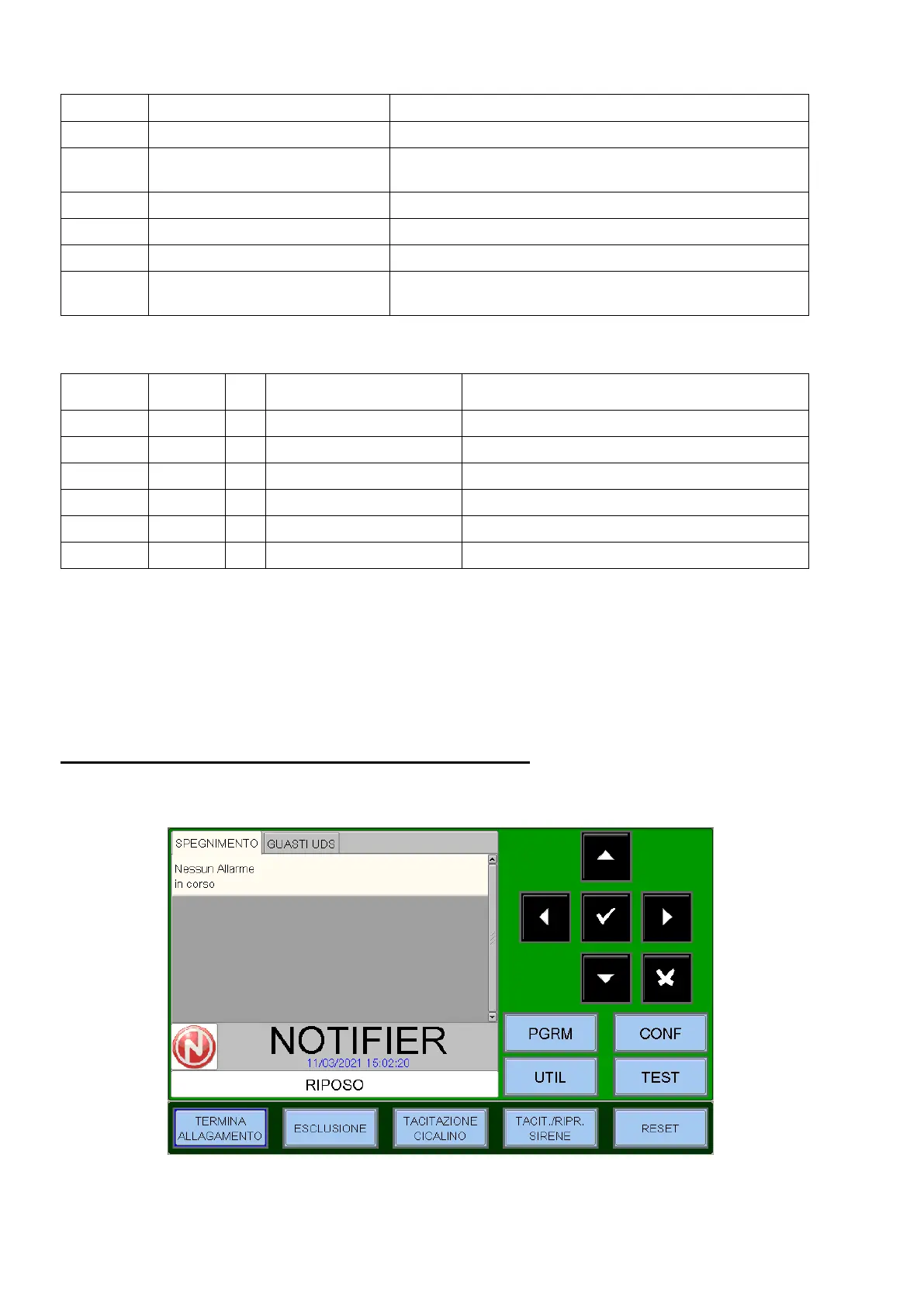
4 - FRONT PANEL CONTROLS AND SIGNALS
Commands are given via the interface on the 7" colour touch display.
 Loading...