Do you have a question about the Notifier NCS and is the answer not in the manual?
Details the mounting and connection procedures for the Network Control Station (NCS) and its components.
Lists related documents for a comprehensive understanding of NCS features and products.
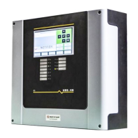
Explains the NRT-NET interface card, its function, and connection to the network.
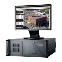
Details the components included in the Network Control Station (NCS) kit.
Covers the requirements and connections for primary and secondary power for the NCS.
Provides step-by-step instructions for connecting the NRT-P3 computer.
Instructions for installing the monitor (MON-19BLK) for the NCS system.
Specific steps for connecting the MON-19BLK monitor to the junction box and NRT-P3.
Details the requirements and wiring for NCS Uninterruptible Power Supply (UPS) supervision.
Wiring information for supervising the NCS computer, monitor, and printer with a UPS.
Wiring diagram for supervising the NCS printer's UPS connection.
Instructions for connecting the protective cover with strain relief for wiring.
Information regarding peripheral devices that can be connected to the NCS.
Steps for connecting a line printer to the NCS for printing alarm and trouble signals.
Specifies the required PC setup configurations for running the NCS program.
Information on installing and configuring the NCS software and related applications.
Detailed steps for installing the NCS software on Windows NT or Windows 2000.
Details on installing NCS Graphics Printer and NCS Line Printer.
Instructions for copying NCS information onto a CD using the Read/Write CD drive.
Steps to configure Secure Desktop for NCS operation and UL-864 compliance.
Explains how the Network Control Station (NCS) annunciates system signals on Noti•Fire•Net.
Describes the NCS database, including history and graphics, and power-up checks.
Details the history database content, storage, and accessibility.
Explains the graphics database content and modification via the Graphics Setup Program.
Covers initialization processes like data refresh upon NCS power-up or node joining.
Explains the NCS data refresh function for updating point information.
Details how to manually invoke the data refresh command for specific nodes.
Instructions for launching the NCS application from the start-up window.
Overview of the NCS graphical interface, including main windows and components.
Describes the main input/output window for displaying alarms and troubles.
Explains the Auto-Vectoring function that directs the display to the highest priority event.
Identifies the title bar which displays the name of the current window.
Details the menu bar, listing available menus and commands for each window.
Describes the graphic floor plan as the main screen area for building layouts.
Explains the key map area as an overview of graphics for navigation or context.
Displays unacknowledged, off-normal events, color-coded by event type.
Shows acknowledged events, moved from the unacknowledged event window.
Tools for navigating between different graphic representation screens.
Displays the current system time with second resolution.
Window used to display a company logo, customizable via GSP.
Provides quick access buttons for displaying event counters and detailed event windows.
Displays status indicators for different event types on the NCS interface.
Area for issuing commands like Acknowledge, Reset, and Signal Silence.
Shows the name of the current NCS operator and provides access to operator info.
Overview of programming options accessible via the menu system.
Provides access to System Setup, Network Operations, and Archive History Database.
Accesses the System Administration dialog box with various NCS programming options.
Allows setup, monitoring, and status checking of network nodes connected to the NCS.
Option to archive the current history database and open a new one.
Used to import graphics into NCS or invoke the Graphics Setup Program.
Details programming graphics using the Graphic Setup Program (GSP).
Provides access to edit speech files, compact databases, and view network statistics.
Allows access to help files and displays software copyright and part number.
Describes the system's state during normal operation with no alarms or troubles.
Explains how the NCS reports and handles trouble signals from fire alarm panels.
Details how the NCS reports and handles alarm signals from fire alarm panels.
Describes how the NCS reports supervisory, security, and pre-alarm signals.
Overview of menu options for operating the NCS, including File and Operator menus.
Provides options for printer setup and exiting the NCS application.
Command to exit the NCS program and return to the Windows environment.
Allows users to Login, Logout, and Change Password for the NCS.
Process for gaining access to the NCS by entering a username and password.
Procedure for exiting the NCS application and returning to the OS.
Allows a user to change their current password for NCS access.
Provides commands for acknowledging events, system reset, and signal silence.
Allows viewing of event counters, detailed events, current events, and history manager.
Displays the count of new and total events for alarms, troubles, and other categories.
An advanced display interface showing all off-normal events on the network.
Displays all network and local events, and system messages received by the NCS.
Lists all disabled devices in the system and provides options to re-enable them.
Records all operator actions and system events (alarms and troubles).
Allows viewing different graphic building representations via navigation menus.
Lists trouble messages specific to the NOTI•FIRE•NET™ network environment.
Displays programming and status for detectors supported by the NCS.
Shows programming and status for control and monitor modules.
Displays programming and status for zones within the system.
Shows programming and status for annunciator points on the NCS.
Provides access to system data I parameters for points.
Provides access to system data II parameters for points.
Provides access to system data III parameters for points.
Details how the History Manager integrates with and operates alongside the NCS.
Explains how to open and manage previously archived history databases.
Displays a list of operators who have logged onto the system and their last login times.
Shows the current number of entries displayed in the history database.
Describes the History Manager's functionality when operated independently from NCS.
Allows operators to view events using specific search criteria.
Enables customization of displayed columns in the History Manager.
Instructions for printing the current or stored history database.
Details the process of archiving the current history database for backup.
Explains the NCS's automatic history file backup feature.
Used to upload or download databases from nodes and schedule uploads.
Covers scheduling uploads on a monthly or 'one shot' basis.
Describes GSP operation when called from the NCS, and database updates.
Overview of the Graphic Setup Program (GSP) interface and its windows.
Shows screen linking through groups and allows navigation to floor plans.
Displays devices linked to groups and allows modification of group settings.
Shows screens and associated devices, allowing direct editing of devices.
Displays current screen information, including description and file names.
Contains shortcut buttons for graphic operations like creating devices and editing plans.
Describes floor plan bitmaps, their measurements, and storage requirements.
Details managing graphic floor plans, including adding and selecting them.
Step-by-step instructions for adding new floor plans and keymaps to the NCS.
Procedure for selecting floor plans for editing purposes.
Instructions on how to delete screens and associated elements.
Explains how to link key maps to floor plan diagrams for navigation.
Describes setting a 40-character title for floor plans.
How to add instruction or warning text applicable to displayed screen areas.
Describes keymaps as bitmaps displayed above the floor plan for overview.
Details options available through the menu bar, including File, Screens, and Devices.
Option to exit the Graphic Setup Program and return to the NCS.
Options for creating, selecting, deleting graphic screens, and setting keymap links.
Menu options for managing groups, detectors, modules, zones, and labels.
Allows customization of the toolbar and viewing screen statistics.
Option to edit the site logo using Paint Shop Pro.
Information on adding and managing device graphics, including icons and bitmaps.
Accesses help files and displays software information.
Details on adding device graphics like groups, detectors, modules, and zones.
Explains how to graphically represent devices and assign descriptions.
Describes symbols associated with detectors, including active, trouble, and disabled states.
Explains symbols for modules and options like disabling or activating them.
Describes symbols for zones, indicating active and disabled device states.
Information on linking sound, document, and picture files to devices.
Describes adding bitmaps for additional information on floor plans.
Explains how to place and link navigational buttons to other screens.
Procedure for deleting buttons, devices, or information labels from a screen.
How to find specific devices using label or address within the NCS.
Defines rules for setting up device graphics, including group hierarchy and screen placement.
Allows creation of screen hierarchies for displaying off-normal devices.
Details the two levels of grouping (Level 1 and Level 2) for device association.
Requirements for Level 1 groups, including state bitmaps, descriptions, and labels.
Requirements for Level 2 groups, including association with Level 1 groups.
Lists restrictions for associating devices and groups within floor plans.
Explains how group navigation works when events occur and auto-vectoring is off.
Templates for defining device setups and grouping graphic file options.
Specifies bitmap file groupings for modules, detectors, zones, and buttons.
Hot templates are setups of specific devices, allowing easy copying of options.
Describes how to customize the bitmap appearing next to the keymap area.
Lists essential files required for creating floor plans and using PaintShop Pro.
Specifies required directories and files for NCS operation.
Steps to disable the Windows 2000 login box for automatic NCS startup.
Steps to re-enable Windows 2000 security features after disabling.
Instructions for installing PaintShop Pro 7.0 software.
Steps to install and configure Secure Desktop software for UL-864 compliance.
Depicts AFP-200 and AFP-300/400 messages as they appear on the NCS.
| Type | Network Control Station |
|---|---|
| Power | 24 VDC |
| Networking | Ethernet |
| Operating Temperature | 32°F to 120°F (0°C to 49°C) |
| Humidity Range | 10% - 93% RH, non-condensing |
| Max Number of Devices | Up to 200 devices |
| Backup Battery | Optional |