Installation NCS Mounting and Connections
10 NCS Manual PN 51095:B1 3/08/02
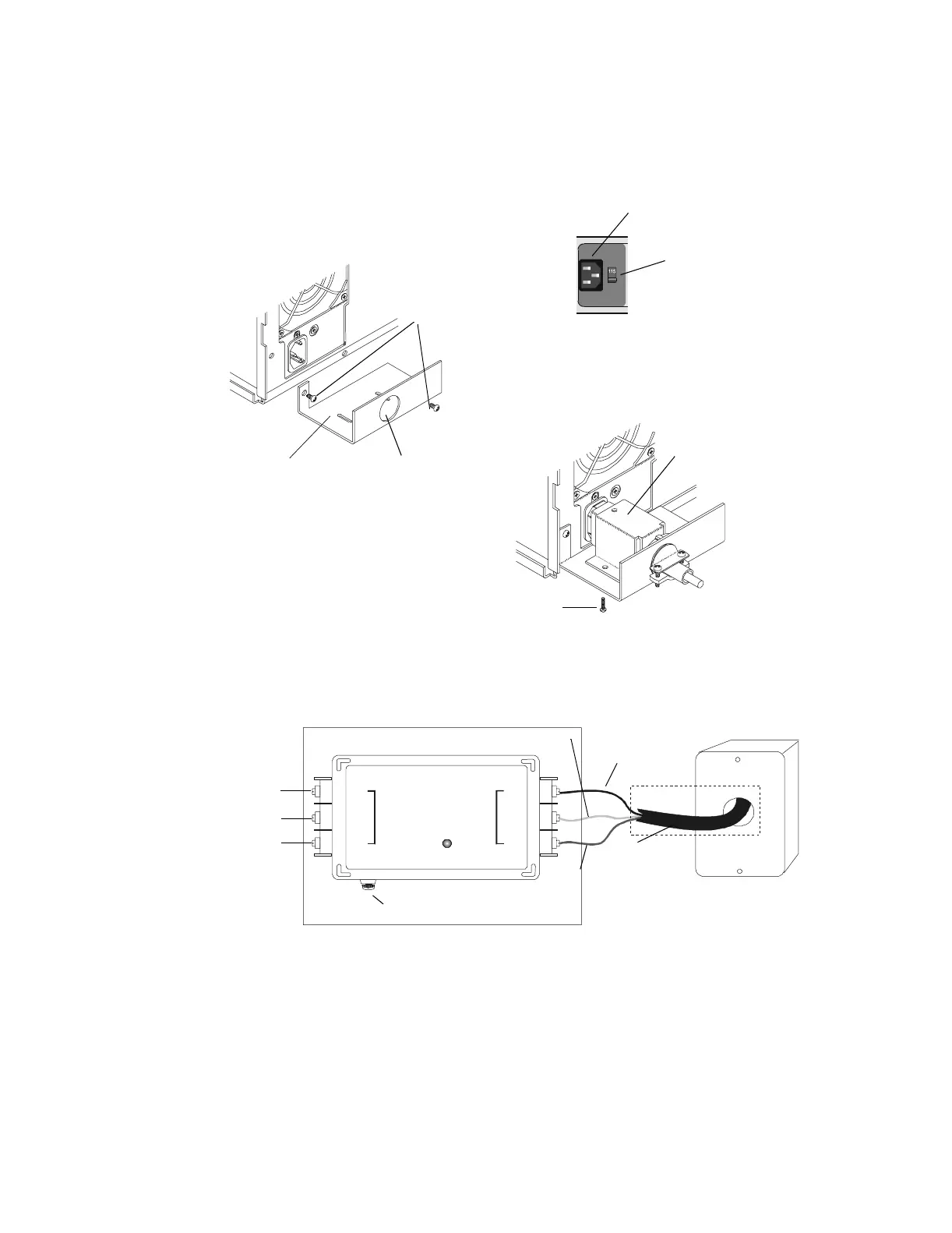
• The NRT-P3 requires 115 VAC, 50/60Hz primary power or 230 VAC, 50/60 Hz primary power depending upon the
position of the voltage selection switch shown in Figure 1.2 and Figure 1.3.
• Where an NCS is required, the use of a supervised Uninterruptable Power Supply (UPS) is also required (see Figure
1.6)
• The NCS is not suitable for use as a receiving unit.
• The front power switch for the NRT-P3 has been permanently fixed in the ON position.
Figure 1.3 Attaching the PCLB-6 to the NRT-P3
Figure 1.4 Connecting the Power Cord and Primary AC Power
to the Power Line Protector
1.1.6 Monitor Installation
1.1.6.1 Installing the MON-19BLK
The following steps must be completed when connecting the MON-19BLK to the Junction Box and
NRT-P3 (refer to Figure 1.5).
1. Connect the AC Power Cord on the MON-19BLK to the HSP-121B Junction Box.
2. Connect the DB-15 video cable to the video card slot on the NRT-P3.
Power Cord
Voltage selection
Switch
PCLB-6
(without cover)
Mounting Screws
Knockout
PCLB-6 Cover
Mounting Screw
PCLB5Bb.cdr
nrtpwcrd.cdr
PCLB5Ba.cdr
AC
NEUT
GND
AC
NEUT
GND
L
I
N
E
E
Q
U
I
P
Ground - Green
Neutral - White
AC - Black
Power Cord
Fuse
To 115 VAC, 50/60
Hz Primary Power or
230 VAC, 50/60 Hz
Primary Power
Black
White
Green
HSP-121B
Conduit
PCLB-6
Light ON - Normal
Light OFF - Requires Service
15 AMPS
MAX
Junction Box
hsp-121b.cdr
www.PDF-Zoo.com