The Graphic Setup Program Program Layout
60 NCS Manual PN 51095:B1 3/08/02
Section 5 The Graphic Setup Program
The Graphic Setup Program allows the creation of floorplans and devices as well as associating
information about each device.
5.0.1 NCS Integrated Operation
If the GSP is called up from the NCS, all operations are identical. However, when the GSP is
exited, graphics.mdb is not automatically updated. Instead, the database can be updated in the NCS
using the Update Graphic Database command under the Graphics menu. If the NCS is not running
at the time the database is updated, the database can be updated once the NCS is powered up, and
the update command is executed.
In both the Standalone and NCS integrated operations, on power-up the existence of the backup
database will be checked. If it exists, then a dialog box will be displayed indicating that it was
found. The user then has the option to use this database, or the graphics database. If the graphics
database is chosen, recent edits might be lost.
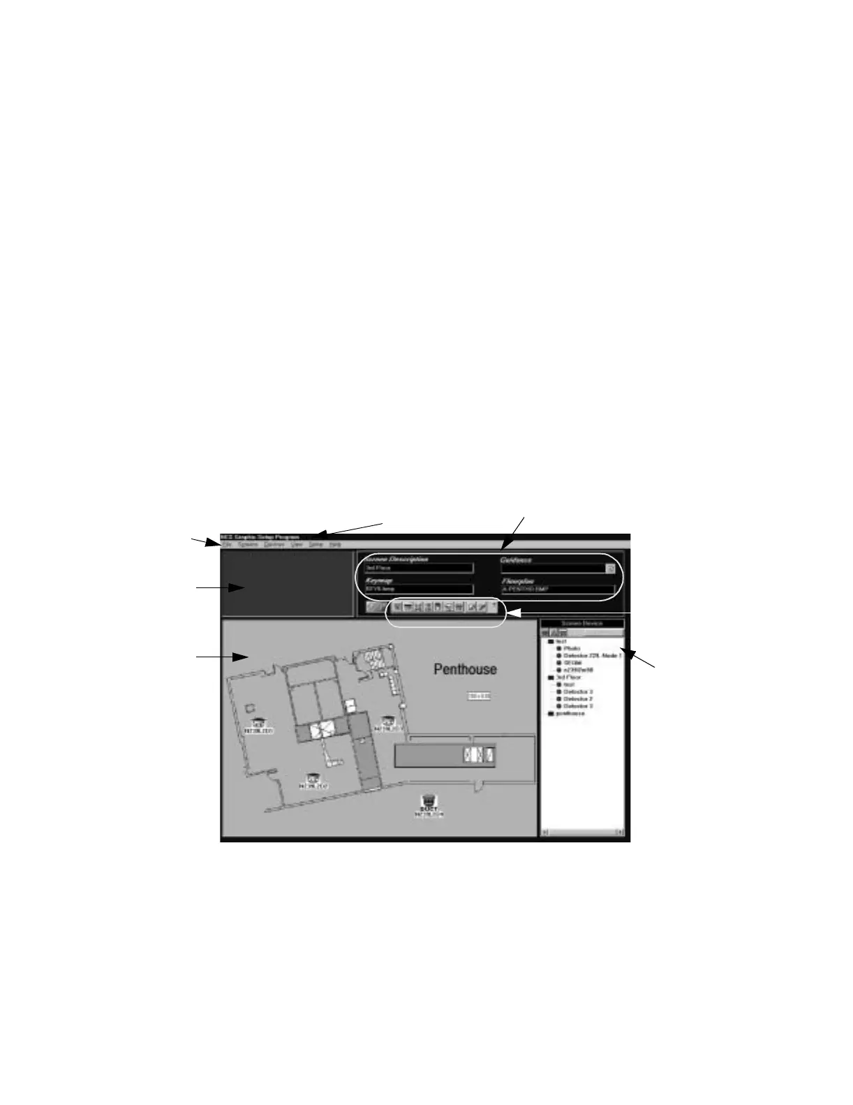
5.1 Program Layout
The Graphic Setup Program (GSP) consists of several different windows. The main graphics area
and key-map area have the same size and location as in the NCS. This allows the user to place
screen floorplans and devices, and see them exactly as they would appear in the NCS. Refer to
Figure 5.1.
Figure 5.1 Graphic Setup Program Interface Window
In addition, the top area has room for displaying the current screen information and command
buttons. The area to the right of the main graphics screen contains the Tree View Window which is
similar to a Windows Explorer type structure, refer to Figure 5.2. The Tree View Window offers
three different views of the system:
Graphics Area
Key-Map Area
Information Window
Toolbar
Tree View Window
(Screen Device View)
Menu Bar
Title Bar
ncsgspint.jpg
www.PDF-Zoo.com