Installation NCS Mounting and Connections
8 NCS Manual PN 51095:B1 3/08/02
1.1.2 NRT-NET Interface Card
The NCS communicates with Noti•Fire•Net through the Network interface card (NRT-NET) and
the Media Interface Board (MIB). The NRT-NET interface card plugs directly into a computer
expansion slot located on the NCS computer. The MIB, which supports the physical connection to
the network, plugs onto the NRT-NET card to complete the network interface. The NRT-NET
interface card provides the following features:
• Allows the NCS computer to communicate on Noti•Fire•Net
• Accepts the following choices of Media Interface Boards:
- twisted-pair (MIB-W)
- Fiber optic (MIB-F)
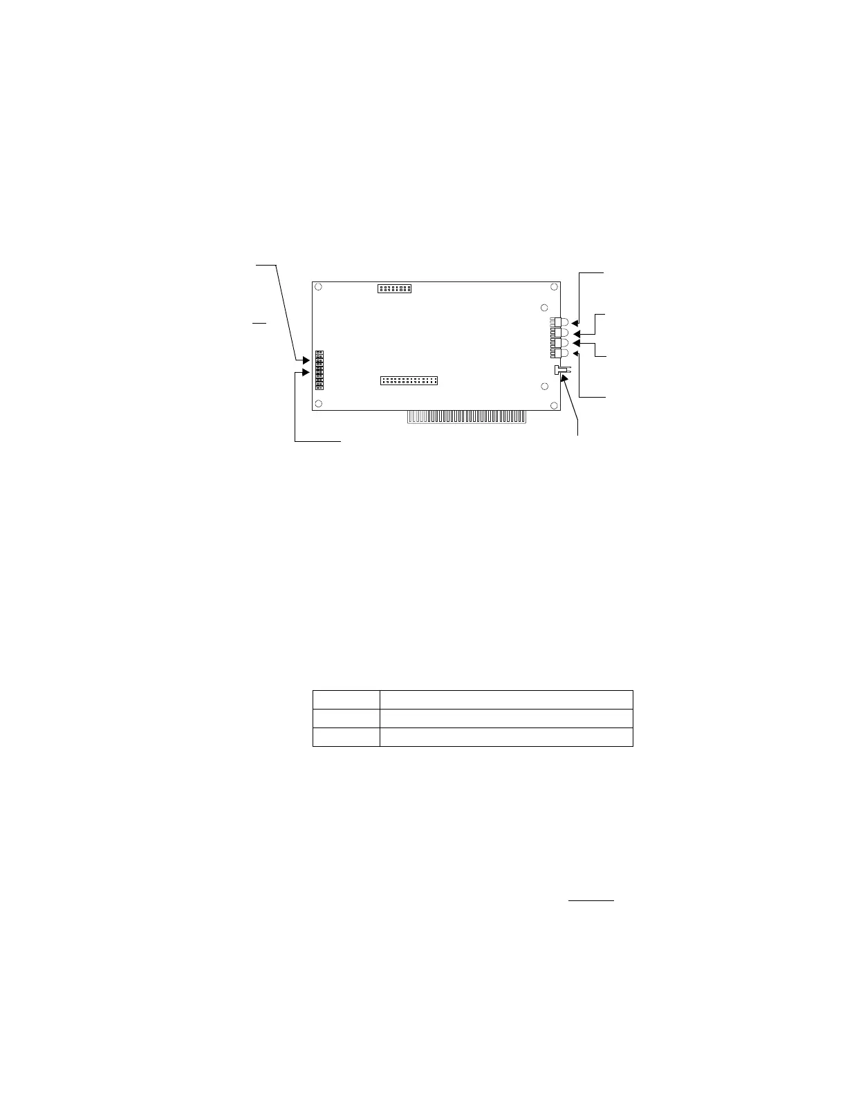
Figure 1.1 NRT-Net Card
1.1.3 NCS Equipment
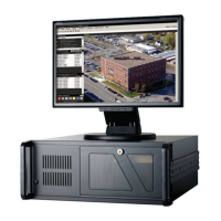
The Network Control Station is a kit comprised of:
• a computer
• A MON-19BLK monitor (UL 864 Listed 19 inch monitor)
Refer to Table 1.2 for model numbers and components.
Note: The monitor and mouse, as well as the printer if one is used, must be installed in the same room as the NCS in order
to comply with UL listing requirements.
A PRN-5 printer can be ordered separately.
The NCS computer is referred to in this manual as the NRT-P3. Table 1.2 lists the NCS model numbers
that include computers referenced as NRT-P3.
Table 1.2 NCS Equipment Options
1.1.4 Primary and Secondary Power
The NCS requires connection to a separate dedicated primary AC fire alarm circuit, which must be
labeled "FIRE ALARM." This AC circuit must connect to the line side of the main power feed of
the protected premises. No other equipment can be powered from the fire alarm circuit. The
primary AC circuit wire run must run continuously, without disconnect devices, from the power
source to the NCS. Overcurrent protection for this circuit must comply with Article 760 of the
National Electrical Code as well as local codes. Where an NCS is required
, the use of an UL-864
approved supervised UPS is also required. When using a UPS, NCS input voltage must be 115
VAC. The use of 230 VAC is not permitted when employing a UPS.
1.1.5 Connecting the NRT-P3
The following steps must be completed when connecting the NRT-P3 (refer to
Figure 1.2 and Figure 1.3).
Model # Components
NCS-M19F NCS computer, mouse, 19" monitor, fiber optic data link
NCS-M19W NCS computer, mouse 19" monitor, wire data link
LED illuminates to indicate
that NFN is receiving data.
LED illuminates to indicate
that NFN is transmitting data
LED illuminates to indicate
activity on Channel A.
LED illuminates to indicate
activity on Channel B.
Monitors normally closed contacts of
uninterruptible power supply (UPS). If
unused, cover pins using supplied jumper.
JP3, IRQ7
The jumper
provided must
cover these pins if
the NCS is not
an
NRT upgrade.
Note: If the NCS
is an NRT
upgrade, the pins
at JP3, IRQ3 must
be covered.
JP6 - Present on the NRT-NET card of an
NCS or later model NRT. Do not remove
the jumper at JP6, which is set at 300H.
www.PDF-Zoo.com