Device Icons The Graphic Setup Program
NCS Manual PN 51095:B1 3/08/02 69
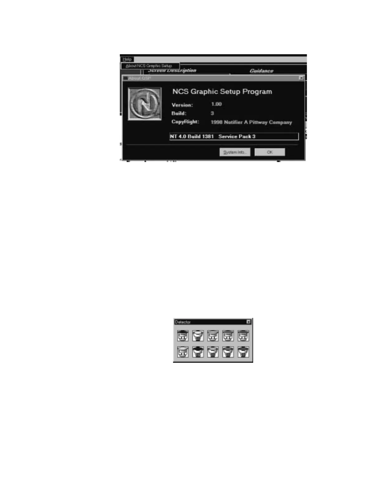
5.4.6 Help
Figure 5.28 The Help Menu
5.5 Device Icons
After a floor plan and keymap screen have been created, Device Graphics can be added. Device
Graphics include Level1 Groups, Level2 Groups, Devices (detectors, modules and zones),
Navigation Buttons, and Information Labels. All device bitmaps must be stored in the
{install}\device directory, Groups must be stored in the {install}\group directory.
5.5.1 Devices
A symbol can be used to graphically represent a device (detector, module or zone) in the fire alarm
system. In addition to a graphical representation of the device, the user can assign device
descriptions and link pictures, documents and sound to the device. The NCS does not permit one
device to be displayed on multiple screens; a device can only appear on one screen.
A new device can be added to the system by using the Devices Menu command or through the
toolbar. When using the toolbar, select the appropriate detector, module or zone you would like to
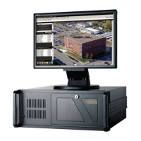
add. After this command is executed, a library of icons will be displayed to select a symbol
representing the device, refer to Figure 5.29.
Figure 5.29 Detector Library of Icons
Once a device is selected, a new device dialog box is displayed where the user can enter address
information about the device, Figure 5.30. For detectors, modules and zones, options are available
to link a sound file, document and/or picture to the symbol. In addition, each of these devices can
be linked to a group. If grouping is to be used, the groups and group screens should be created
before actual devices. Devices can also be set to auto-vector, in this case the Auto-Navigate option
must be selected.
gsphelp.jpg
detbox.jpg
www.PDF-Zoo.com