Installation NCS Mounting and Connections
12 NCS Manual PN 51095:B1 3/08/02
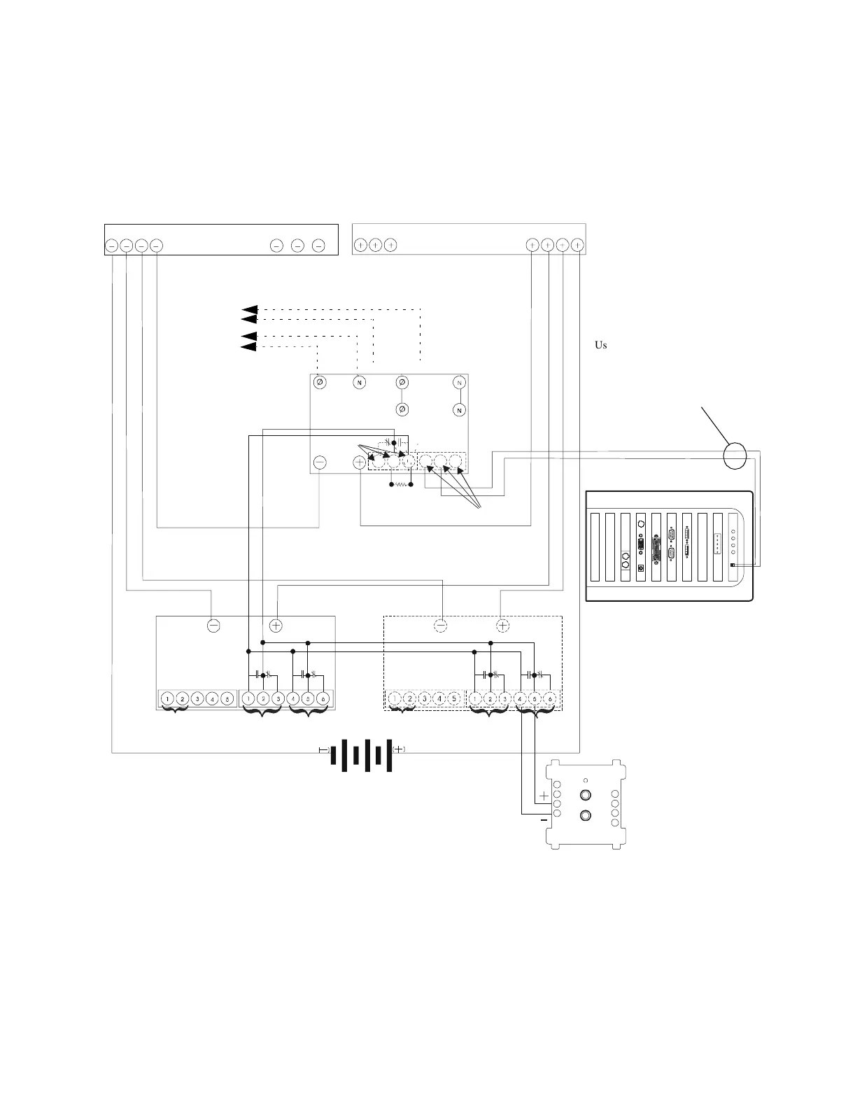
1.1.7 NCS UPS Supervision
1.1.7.1 NCS Computer/Monitor/Printer UPS Supervision
Where a Network Reporting Terminal (NCS) is not ancillary, the use of a supervised 115 VAC
Uninterruptable Power Supply (UPS) is required. Refer to Figure 1.6 and Figure 1.7 for wiring
information. A networked AM2020/AFP1010 or INA with an MPS-24A Power Supply must be
located within three feet (.9144 m) of the UPS and wiring must be in conduit.
Figure 1.6 NCS Computer UPS Supervision
+
-
Use cable P/N 71033 (supplied
with the NCS) from
NRTNETPCB to UPS. Cut and
strip wires as needed. Make all
connections in conduit.
Negative Bar
Positive Bar
To AC Power of
NCS, Printer, or CRT
AC Input
Inverter
Failure
DC/AC Inverter
AC
Load
115 VAC
AC Line
115 VAC
Note: The Inverter is equipped
with automatic transfer. Refer to
the schematic in the instruction
manual for internal wiring.
Note: Wiring should be in the same
cabinet or use less than 3 feet of conduit.
47k ELR
Utility Failure
(optional)
DC
Output
DC
Output
Charger 1
Charger 2
NCSsupsfsonyxnrtnet.cdr
NC
NC
COMM
NRT-P3 Computer
FMM-1
Low
Current
Rectifier
Failure
Remote
Equalize
Remote
Sense (-)
Remote
Sense (+)
Load
Sharing
Low
Current
Rectifier
Failure
Remote
Equalize
Remote
Sense (-)
Remote
Sense (+)
Load
Sharing
www.PDF-Zoo.com