Programming NCS Graphical User Interface
24 NCS Manual PN 51095:B1 3/08/02
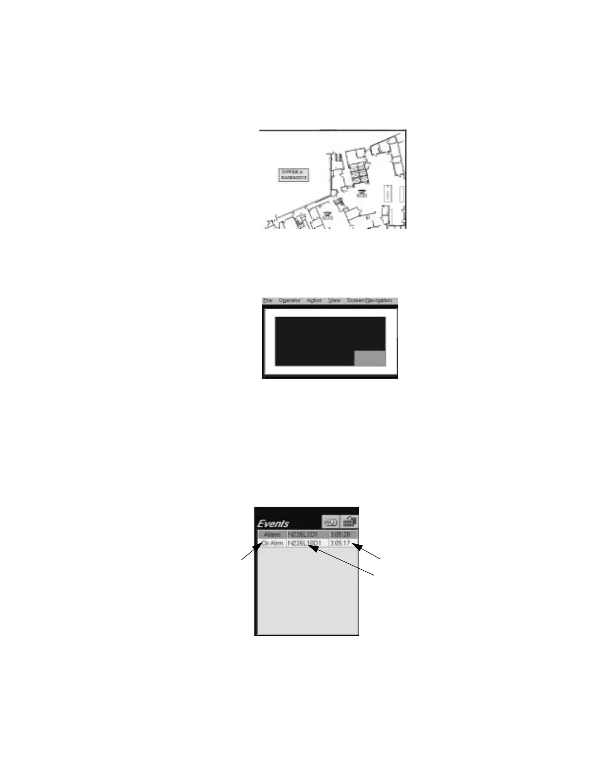
2.5.1.4 Graphic Floor Plan
The graphic floor plan is used to view the graphic layout of a building, high-rise or campus type
setting. It comprises the largest screen area in the NCS. It will allow an operator to see a diagram
of any specific area of the monitored network and give the operator information about the facility
area and the monitored devices. The graphic screen is comprised of bitmaps with devices
overlaying them. Refer to Figure 2.6.
Figure 2.6 Example of a Graphic Floor Plan
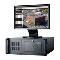
2.5.1.5 Key Map Area
The key Map Area is an overview of the graphics used in the system. It can be set up for navigation
or simply as an accompanying view of the foreground, refer to Figure 2.7.
Figure 2.7 Key Map Area
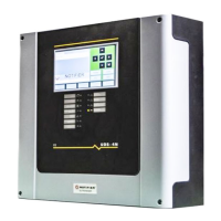
2.5.1.6 Events Window
The Events window displays the first of 12 unacknowledged, off-normal events on the network.
The events are grouped by event type (i.e., fire alarm, security alarm, supervisory alarm, and
trouble), and sorted by time within the group, displaying the oldest event first and the newest event
last. The highest event group is displayed on top of the window, the lowest event group on the
bottom of the window, refer to Figure 2.8. All events in this window are color coded. Fire alarms
are designated red, Security Alarms as blue, Supervisory Alarms as orange, Trouble Conditions as
yellow, and Pre-Alarms as cyan.
Figure 2.8 Events Window
The information displayed consists of the event type, the address, and the time that the event was
received (assigned by the NCS). A detail button is provided to expand the event box to display all
events, as well as provide more detailed information for each event. Refer to “The Detailed Events
Window” on page 44 for more information on the Detailed Event Box.
ncsbase.jpg
ncskeymap.tif
Event Type
Address
Time
firevent.tif
www.PDF-Zoo.com