UDS-4 Installation and user manual PAGE - 31
UDS-4_manu M--203.1-UDS4N-ENG Rev A.1 NOTIFIER ITALIA
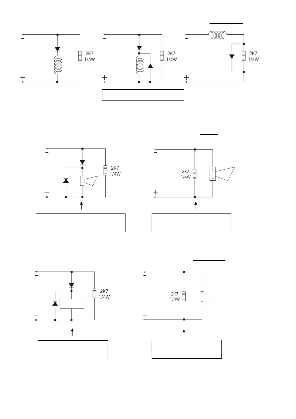
7.4 - Possible connection diagrams for solenoids on the "Shutdown" output
Note: The polarities shown in the terminals refer to the "Stand-by" condition of the UDS-4N panel.
7.5 - Possible connection diagrams on the "Siren" output
Note: The polarities shown in the terminals refer to the "Stand-by" condition of the UDS-4N panel.
7.6 - Possible connection diagrams for the "Pre-alarm" output
Note: The polarities shown in the terminals refer to the "Stand-by" condition of the UDS-4N panel.
 Loading...