PAGE - 32 Installation and operating manual UDS-4
NOTIFIER ITALIA Doc. M--203.1-UDS4N-ENG Rev A. 1 UDS-4_manu
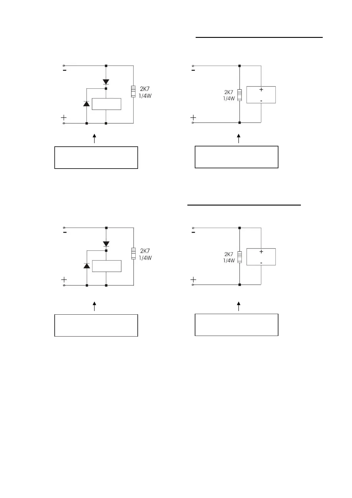
7.7 - Possible connection diagrams for the "Extinguishing system in lockout"
output
Note: The polarities shown in the terminals refer to the "Stand-by" condition of the UDS-4N panel.
7.8 - Possible connection diagrams for the "Pilot Cylinder/Directional Valve" output
Note: The polarities shown in the terminals refer to the "Stand-by" condition of the UDS-4N panel.
 Loading...