10
INA 15092:I 05/30/01
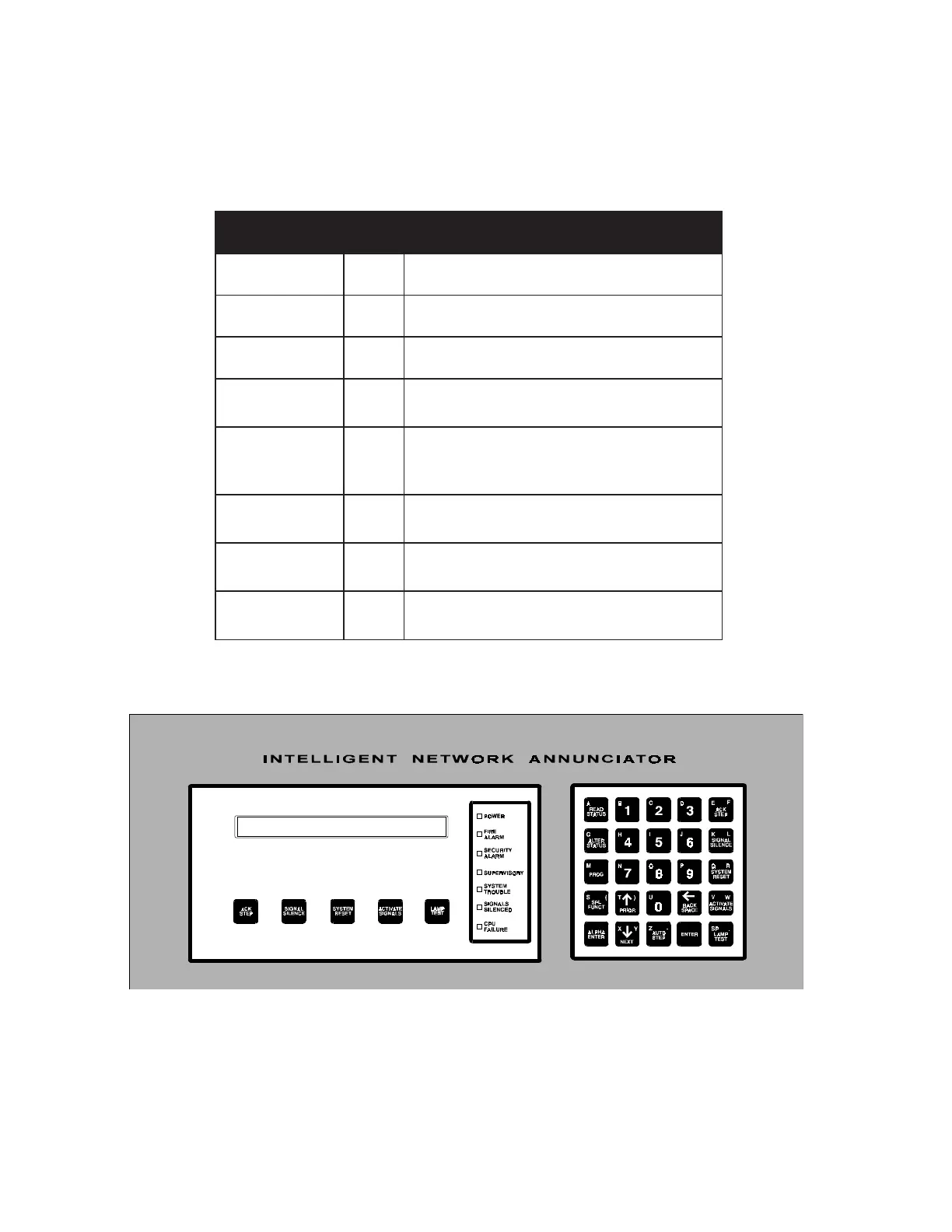
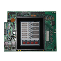
1.3 DIAGNOSTIC INDICATORS AND CONTROLS
The INA has diagnostic LED indicators (refer to Figure 1.31) which aid in troubleshooting and assist the installer in
connecting the system. Refer to Table 1.3-1 for a list of diagnostic LED indicators and their descriptions. The function
keys of the INA, as displayed in Figure 1.3-1, are detailed in Chapter Two of this document.
Table 1.3-1 Identifying LED Indicators
Figure 1.3-1: INA Indicators and Switches
DEL
rotacidnIroloCnoitpircseD
REWOPneerG.nosirewopelihwsetanimullirotacidniehT
MRALAERIFdeR.langismralaerifagnirudsetanimullI
YTIRUCES
MRALA
wolleY.langismralaytirucesagnirudsetanimullI
YROSIVREPUSwolleY
.e.i(langisyrosivrepusagnirudsetanimullI
erif,erusserpwol,lamronffoevlavrelknirps
).cte,ruotsdraug,gninnurpmup
METSYS
ELBUORT
wolleY
rolangiselbuortagnirudsetanimullI
.langisssecorplacitircnon
SLANGIS
DECNELIS
wolleY
noitacifitontahtetacidniotsetanimullI
.decnelisneebevahsecnailppa
ERULIAFUPCwolleY
eruliafrossecorporcimetacidniotsetanimullI
.)dilavnisinoitamrofniyalpsidDEL/DCL(
www.PDF-Zoo.com