20
INA 15092:I 05/30/01
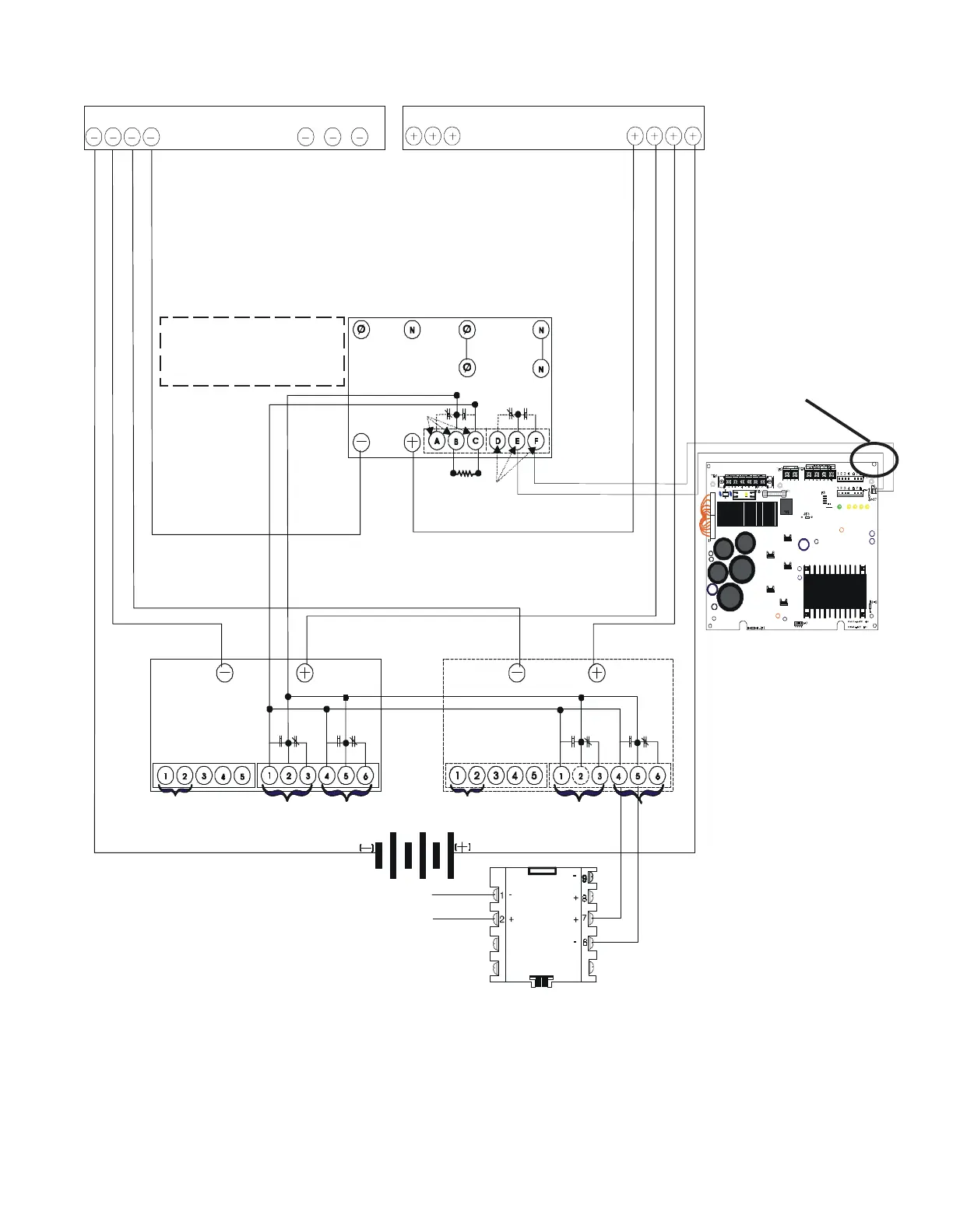
Figure 2.5-2 Wiring Diagram for UPS Supervision for Printer/CRT
Use cable P/N 71033 from
MPS-24A connector P5 to
UPS. Cut and strip wires
as needed. Make all
connections in conduit
Negative Bar Positive Bar
AC
Load
AC Line
DC/AC Inverter
Inverter
Failure
Utility
Failure
47k ELR
(Optional)
DC
Input
Note: Wiring should be in the
same cabinet or use less than
3 feet (0.9 m) of conduit
Note:
The inverter is equipped with
automatic transfer. Refer to the
schematic in the instruction
manual for internal wiring.
To MPS-24A (P5)
DC Output
DC Output
Charger #1
Charger #2
TS-2
TS-2
TS-1
TS-1
Remote
Equalize
Remote
Sense (+)
Remote
Sense (-)
Load Sharing
Rectifier
Failure
Low
Current
Remote
Equalize
Remote
Sense (+)
Remote
Sense (-)
Load Sharing
Rectifier
Failure
Low
Current
Battery
SLC
Software Type ID
MTRB
UPS3a.cdr
MMX
www.PDF-Zoo.com