INA 15092:I 05/30/01
25
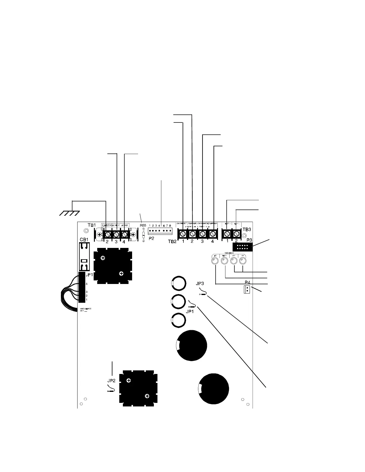
2.7.2 THE MAIN POWER SUPPLY (MPS-24B OR MPS-24BE)
The MPS-24B/MPS-24BE may be mounted externally or in the same cabinet (CAB-3) as the INA. When powered from a
MPS-24B/MPS-24BE mounted in the same cabinet, power is supplied to the INA through the main power harness (from P2
on the MPS-24B/MPS-24BE to J4 or TB3 on the INA). For calculation of the primary and secondary power requirements,
refer to Appendix A.
Cut JP2 to disable the battery charger
when employing the CHG-120 Remote
Battery Charger.
Earth Ground
Connect to chassis with a
Grounding Cable Assembly
(Cable # 71073).
Not used on the INA
Figure 2.7.2-1 Field Wiring the MPS-24B/MPS-24BE
Four-Wire Smoke Detector/Annunciator Power
24 VDC (200 mV ripple), 200 mA max. Filtered and resettable*.
Power-limited but when used for four-wire detectors, must be su-
pervised by a UL listed Power Supervision Relay. Power run to
ACS Annunciators is inherently supervised.
Cut R55 to
Disable
Earth Fault
Detection.
Power Harness
Connect to J4 on the
INA
Power Ribbon Connector
Connect to J9 on the INA
Neutral
Hot
Secondary Power
27.6 VDC, 6.5 to 17 AH. Supervised and power-
limited. Fast charge =750mA max., trickle charge
= 20 mA (typ).
Battery +
Battery -
* Cut JP1 to make Four-
Wire Smoke Detector
Power on TB2 Terminals 1
and 2 a non-resettable cir-
cuit.
JP3 must be cut for
use with the INA.
LED Indicators
Earth Ground Fault
Battery Fail
AC Power Fail
Primary Power
120 VAC, 50/60 HZ, 1.8 amps max. (MPS-24B)
220/240 VAC, 50/60, 0.9 amps max (MPS-24BE)
+
_
_
+
Notification Appliance Power
24 VDC power-limited, RMS-regulated, non-
resettable, 2.0 amps (in alarm) max. Power is super-
vised by output module (such as an ICM-4). Not
for annunciators!
www.PDF-Zoo.com