Page 2 of 2 — 990-077
ORDERING
INFORMATION
Part No. Description
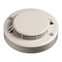
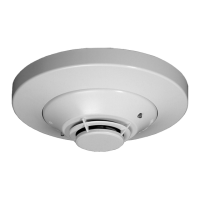
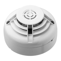
SD-851E Conventional
Photoelectric Smoke
Detector
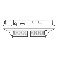
Base:
B401 Standard Base
B401D Standard Base with
schotty diode
B401R Resistor base with 470
ohm resistor
B312NL 12V non-latching relay
base
B312RL 12V latching relay base
B324RL 24V latching relay base
Accessories:
S300RPTU Remote Programming
and Test Unit Accessories
S300RTU Remote Test Unit
S300SAT Remote Programming
Interface Unit
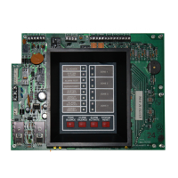
S300ZDU Zonal Display Unit
SPECIFICATIONS
· Dimensions
ü Height: 43 mm
ü Diameter: 102 mm
ü Weight: 75g
· Current Consumption
ü Alarm :50 mA at 24 VDC (limited
by panel)
ü Standby:120µA at 24 VDC
· Operating Voltage
ü 8 to 30 VDC ( Nominal 12/24VDC)
· Environmental Limits
ü -30°C to +70°C
ü Humidity 5 to 95% (non-
condensing)
Wiring Diagram (Diode Base)
INSTALLATION
Each detector can be given a unique
address. When used in conjunction
with the S300ZDU Zone Display Unit the
address will be displayed whenever the
detector is in alarm.
All the features via the hand-held
programming unit are achieved
effectively and effortlessly without the
need to remove the detector or having
to gain direct physical access (other
than by the use of servicing poles in
conjunction with the S300SAT), saving
valuable commissioning/maintenance
time.
They provide the end user with the
confidence to know that the system is
being regularly serviced and that it is
operating at it’s optimum level, with
minimum disruption to business
activities.
In addition to the comprehensive
programming tool, a simple laser based
alarm test unit is also available. The
coded signal transmitted by this device
can instruct the detector to generate a
full alarm condition at a range of up to
5 metres from the detector, and is an
ideal tool for initial commissioning and
routine system testing.
The PhD series detectors incorporate a
bi-colour LED indicator. The integral
LED changes colour according to the
detector’s status: Green = Normal, Red
= Alarm. This benefits the user by
providing clear, instant visual
indication of the detector’s condition.
The Green LED can be programmed for
blink/no blink operation.
A variety of detector bases are
available providing compatibility with
a wide range of Fire Alarm Control
Panels making it ideal for expansions
and retrofit applications. All bases are
fitted with a shorting spring to permit
circuit testing prior to fitting the
detector and have a tamper resistant
feature, which when activated prevents
removal of the detector without the
use of a tool.
+
-
CONTROL
PANEL
End Of
Line Device
Optional
Zonal
Display
Unit
4
1
2
3
4
1
2
3
4
1
2
3
 Loading...