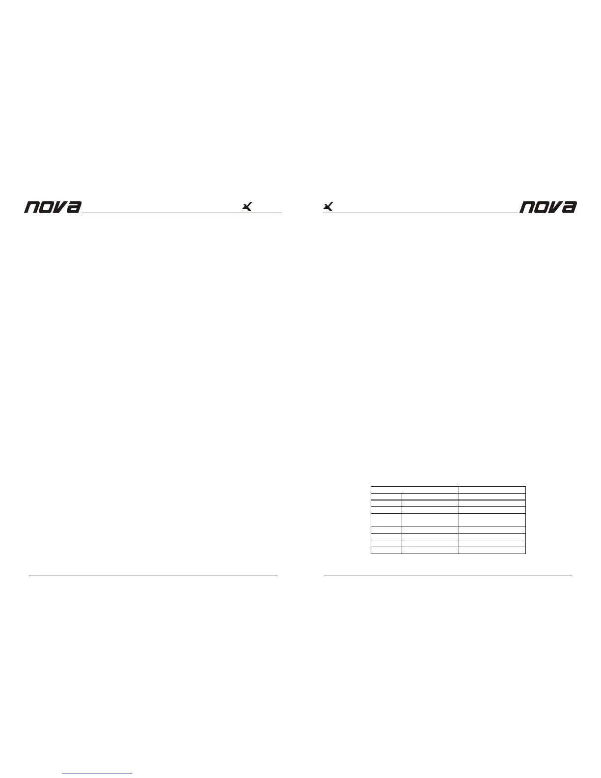
MLS SWITCH SETTING
0 dB
1300 W
2300 W
2900 W [2]
3200 W [1]
LOAD
8 ohms
4 ohms
2 ohms
CONFIGURATION
Stereo (2 channel)
Stereo (2 channel)
Stereo (2 channel)
2600 W
4600 W
5800 W [1]
16 ohms
8 ohms
4 ohms
Bridge mono
Bridge mono
Bridge mono
Reference Manual
Page 8
Reference Manual
Page 5
5. Protect LED
Each channel has a Protect LED that will light when the load connected is lower than 1 Ohm
or amplifier broken.
6. Power LED
The green active LED illuminates to indicate that the amplifier is turned on, and works
correctly.
7. AC power switch
Use this to switch on the amplifier. A soft-start system limits the start-up surges.
8. Fan exhaust ports
Heated air exits the amplifier through the exhaust ports, located on the rear of the amplifier
chassis. Be sure not to block this ports, especially when rack mounting the amplifier.
9. Input connectors
XLR female is provided on each channel for balanced or unbalanced input. Unfortunate
wiring, in the proximity of dimmers or other generalised phase controls, motors, trans-
former, etc. can cause interference into your system. You will hear loud humming or a
bumping noise in the loudspeakers. Balanced wiring suppresses these noises quite
significantly.
10. Impedance matching(OVP switch)
The VOP switches are located on the rear panel. The VOP (Minimum Load Select)switches
Offer impedance matching, so you can drive the X6000 into 2 ohms without increased heat
loss.
As stated earlier, the X6000 can produce 2300 watts into both, 2 and 4 ohms. Use lower
OVP settings when connecting to lower impedance loads as shown in table 1. As can be
seen in table 1, the X6000 can produce output power in excess of 2000 watts.
If the amplifier is going to operate above its maximum operating
0
temperature (90 C).The indicator first comes on as a warning to either turn down the input
level or check the cooling arrangements. Beyond the maximum temperature the amplifier
will mute the input signal. Once the cooling fans have brought the output heat sinks back to
normal operating temperature the input signal is un-muted.
Series
Series
Stereo Mode (standard)
In stereo mode, the channels operate independently, with their input attenuators controlling
the respective channel's level. Recommended minimum nominal load impedance for stereo
operation is 4 or 2 Ohms per channel (as indicated on the specifications). Loudspeakers are
connected to the speakon outputs CH 1 or CH 2. For reference see
Bridged Mono Mode
In Bridged Mono mode, both amplifier channels work with the same input signal, but with
inverse phases. The result is a doubling of the output voltage and thus double the power on
the double impedance. If the amplifier is to be operated in Bridged Mono mode, ONLY one
input may be used CH1. We recommend that you set them to the -0dB (full) position.
Loudspeakers are connected to the speakon output CH 1. For reference see Figure 1.
Parallel Inputs (Link)
In parallel mode both channels' inputs are linked and receive the same signal. The parallel
mode is active if the Link switches are in position "PARA". Both level attenuators are active,
allowing you to set different levels for each channel. Note that only the inputs are connected
in parallel. This is NOT a parallel mono mode. Never connect either positive output terminal
to ground or in parallel. You may use the remaining input connectors to carry the signal to
other amps. NOTE: Always turn off the Link switch when using the amplifier for Bi-amping.
Figure 1
 Loading...