NOTE! The knockout hole on the left side of the EP/2 baseplate
will be blocked by the Ethernet Adapter. If wires run
through this hole, they must be rerouted. Do not route
them under the adapter. The Ethernet Adapter must sit
firmly against the baseplate to ensure a proper connection.
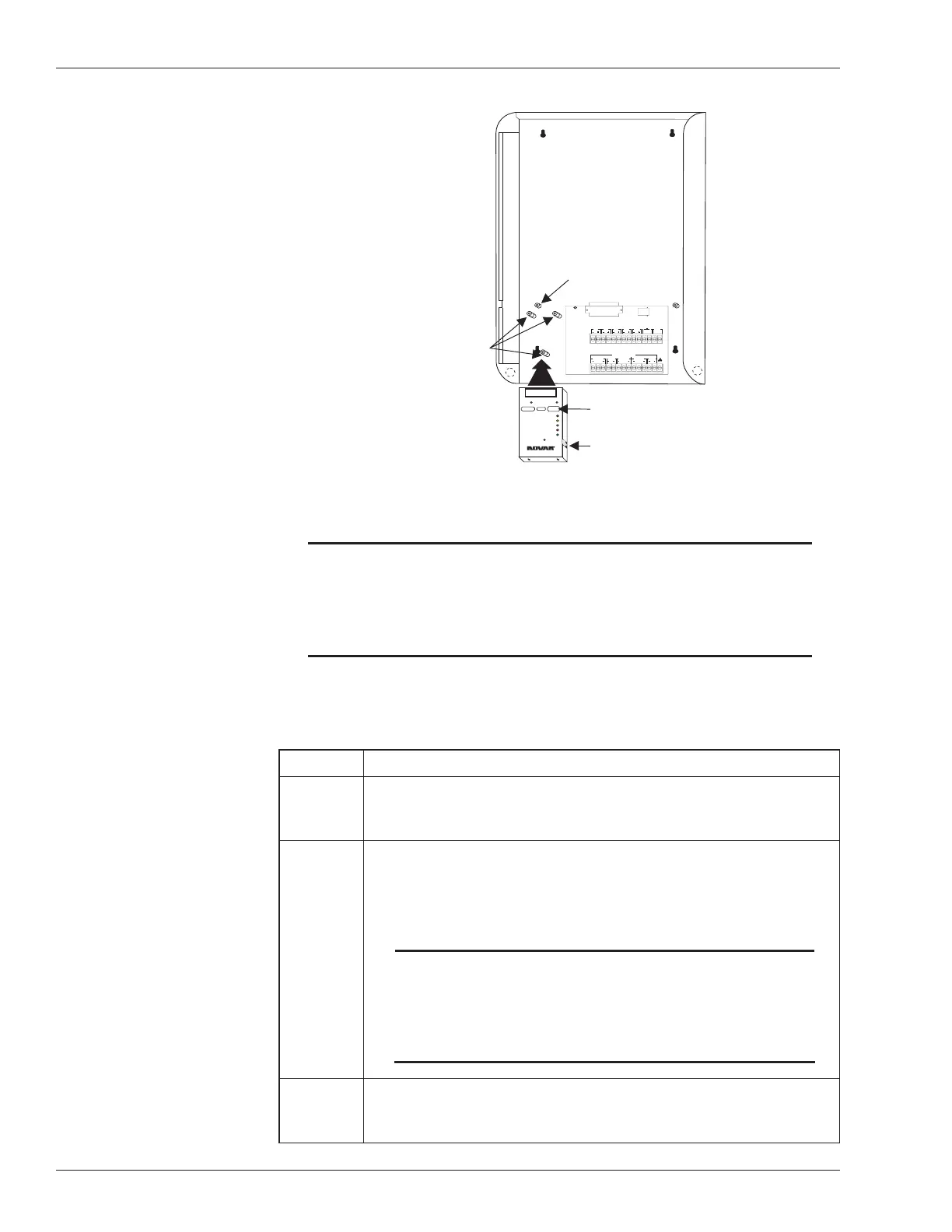
Use the following procedure to mount the Ethernet Adapter to the baseplate of
the EP/2.
Step Procedure
1 Use the hex wrench that came with the hardware kit to loosen
the two screws at the bottom of the EP/2 baseplate and lift off the
cover.
2 Loosen the retaining screws in the two mounting posts on which
the EP/2 electronics assembly sits.
§
Completely remove the screw from the left mounting post (as
indicated in Figure 1).
NOTE! The Ethernet Adapter and the EP/2 electronics
assembly will not connect properly unless the left
mounting post screw is removed and the adapter is
installed before the electronics assembly is
returned to the EP/2 baseplate.
3 Slide the EP/2 electronics assembly up and away from the lip at
the top of the baseplate and set it aside.
continued
2 Doc. #569040000—A 7/30/04
Ethernet
®
Adapter Installation Instructions
1
20
19
37
EXECUTIVE PROCESSOR 2
24V,1A
RS-232 PORT
CLASS2, 5V MAX CIRCUITS
RS-485COMMUNICATION NETWORKS
LAN
'B'M ODULE
DIRECTION DIRECTION
'A'MODULE
SHIELD SHIELD SHIELD
28
27
26
25
24
23
22
21
20
19
18
17
16
15
INPUT
SENSOR
INPUT
SENSOR
OUTDOORLIGHT
OUTDOORTEMP
PULSE
DEMAND
LOSS
PHASE
POWERINPUT
STATUS
1
2
3
4
5
6
7
8
9
10
11
12
13
14
30VA
CLASS2
CLASS2
INPUTINPUTINPUT
TELEPHONELINE
TRANSITION BOARD
NOVARCONTROLS CORPORATION
EMERGENCY
OUTPUTX
24VAC
WARNING
DONOT PLUGTHISMODULE INTOA
POWEREDCONTROLLER!
10BASE-TLAN
CONNECTION
MOUNTCONTROLLER BASEPLATEANDSLIDE
CONTROLLERELECTRONICSINTO PLACE.
RECEIVE
TRANSMIT
POLARITY
COLLISION
GOODLINK
ETHERNET Adapter
MODEL EP/2- EA
®
++
Remove this screw before
mounting the Ethernet Adapter
EP/2 Baseplate with
Electronics removed
Position the Ethernet
Adapter over these
mounting posts and
align the holes so the
screws can be inserted
Ethernet address
(M.A.C. identification)
Insert the Ethernet network
cable here
Figure 1. Ethernet Adapter Module Installation
 Loading...