Step Procedure
4 Align the adapter’s three mounting holes with the three mounting
posts (shown in Figure 1) and carefully push the adapter toward
the baseplate.
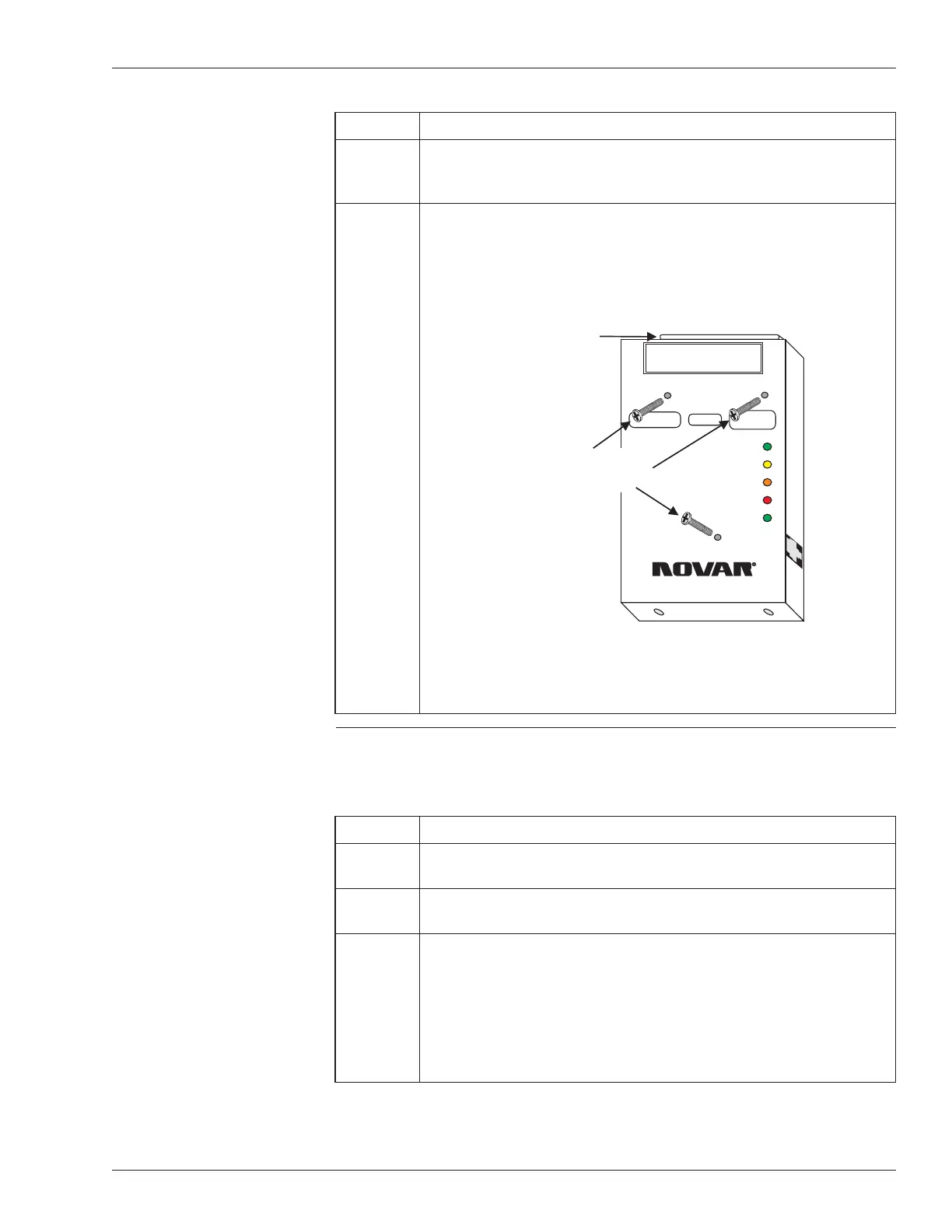
5 Insert the three 1-inch screws included with the mounting kit (see
Figure 2), making certain that they are aligned correctly, and
tighten (using a Phillips screwdriver) to ensure the adapter is
mounted securely.
Making Connections to
the Ethernet Adapter
Use the following procedure to connect the Ethernet Adapter to the EP/2.
Step Procedure
1 Insert the RJ-45 connector from the Ethernet network cable into
the port on the right side of the Ethernet Adapter (see Figure 1).
2 Slide the EP/2 electronics assembly over the lip at the top of the
baseplate and down over the mounting posts.
3 Locate the DB-37 connector on the top of the adapter, carefully
align the pins, and guide the DB-37 connectors on the EP/2
electronics assembly over the connector on the Ethernet Adapter
and over the connector on the transition board of the EP/2.
§
Do not force the connection.
continued
Doc. #569040000—A 7/30/04 3
Ethernet
®
Adapter Installation Instructions
WARNING
DO NOT PLUG THIS MODULE INTO A
POWERED CONTROLLER!
10BASE-T LAN
CONNECTION
MOUNT CONTROLLER BASEPLATE ANDSLIDE
CONTROLLER ELECTRONICS INTO PLACE.
RECEIVE
TRANSMIT
POLARITY
COLLISION
GOOD LINK
ETHERNET Adapter
MODEL EP/2 - EA
®
++
Insert three screws here
to mount the Ethernet
Adapter to the EP/2
DB-37 connector
for connecting
to the EP/2
Electronics
Figure 2. Mounting screw locations on the
Ethernet Adapter