AL PROCESS INDICATOR – INSTRUCTIONS MANUAL – V2.3 G
SAFETY SUMMARY
The symbols below are used on the equipment and throughout this
document to draw the user’s attention to important operational and
safety information.
CAUTION or WARNING:
Read complete instructions prior
to installation and operation of the
unit.
CAUTION or WARNING:
Electrical Shock Hazard
All safety related instructions that appear in the manual must be
observed to ensure personal safety and to prevent damage to either
the instrument or the system. If the instrument is used in a manner
not specified by the manufacturer, the protection provided by the
equipment may be impaired.
PRESENTATION
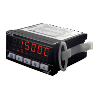
N1500 is a universal process indicator which accepts a large variety
of input signals and sensors. A six-digit LED display shows measured
value and all programming parameters.
Instrument configuration is achieved from the keypad, without any
hardware change. Thus, the selection of input type and alarms
modes, besides other special functions, are accessed and defined
from the frontal keypad.
The user should read this manual thoroughly before using the
instrument. It must be handled with care and should be used
accordingly for best results.
Some of the features are:
• Universal input: Pt100, thermocouples, 4-20 mA, 0-50 mV, 0-5 V
and 0-10 V.
• 24 Vdc power supply for remote transmitter excitation
• Memory for maximum and minimum values.
• Hold and peak hold functions.
• Digital Input;
• Increasing or decreasing display;
• Process Variable (PV) retransmission in 0-20 mA or 4-20 mA
(optional).
• RS485 MODBUS RTU serial communication (optional).
• 3rd and 4th alarm relays (optional).
PROCESS VARIABLE INPUT - PV
The process variable (PV) input type is configured through the frontal
keypad according to the codes shown in Table 1 (refer to INPUT
TYPE parameter "
").
All input types are factory calibrated and no additional calibration is
required.
TYPE CODE MEASURING RANGE
J
Range: -130 to 940 °C (-202 to 1724 °F)
K
Range: -200 to 1370 °C (-328 to 2498 °F)
T
Range: -200 to 400 °C (-328 to 752 °F)
E
Range: -100 to 720 °C (-148 to 1328 °F)
N
Range: -200 to 1300 °C (-328 to 2372 °F)
R
Range: 0 to 1760 °C (32 to 3200 °F)
S
Range: 0 to 1760 °C (32 to 3200 °F)
B
Range: 500 to 1800 °C (932 to 3272 °F)
Pt100
Range: -200.0 to 850.0 °C (-328.0 to 1562.0 °F)
0 – 50 Mv
Linear
Linear. Scalable from -31000 to 31000
0 – 5 V
Linear
Linear. Scalable from -31000 to 31000
0-10 V
Linear
Linear. Scalable from -31000 to 31000
0 – 50 mV
No Linear
Custom Linearization, user configurable
Custom Linearization, user configurable
Custom Linearization, user configurable
4-20 mA
NO
LINEAR
T/C type J linearization. Range: -130 to 940 °C
T/C type K linearization. Range: -200 to 1370 °C
T/C type T linearization. Range: -200 to 400 °C
T/C type E linearization. Range: -100 to 720 °C
T/C type N linearization. Range: -200 to 1300 °C
T/C type R linearization. Range: 0 to 1760 °C
T/C type S linearization. Range: 0 to 1760 °C
T/C type B linearization. Range: 500 to 1800 °C
Pt100 linearization. Range:-200.0 a 850.0 °C
0-20 Ma
Linear
Linear. Scalable from -31000 to 31000
4-20 mA
Linear
Linear. Scalable from -31000 to 31000
Custom Linearization, user defined
Custom Linearization, user defined
Table 1 - Input type codes