EasyManua.ls Logo

Novus N1500 User Manual

Novus N1500
8 pages
To Next Page IconTo Next Page
Page #1 background imageLoading...
Page #1 background image
NOVUS AUTOMATION 1/8
Digital Panel Meter
N1500
DIGITAL PANEL METER
– USER MANUAL – V2.3x P
SAFETY SUMMARY
The symbols below are used on the equipment and throughout this
document to draw the user’s attention to important operational and
safety information.
CAUTION:
Read complete instructions prior
to installation and operation of the
unit.
CAUTION OR WARNING:
Electrical shock hazard.
All safety related instructions that appear in the manual must be
observed to ensure personal safety and to prevent damage to either
the instrument or the system. If the instrument is used in a manner
not specified by the manufacturer, the protection provided by the
equipment may be impaired.
PRESENTATION
N1500 is a digital panel meter which accepts a large variety of input
signals and sensors. A six-digit LED display shows measured value
and all programming parameters.
Instrument configuration is achieved from the keypad, without any
hardware change. Thus, the selection of input type and alarms
modes, besides other special functions, are accessed and defined
from the frontal keypad.
The user should read this manual thoroughly before using the
instrument. It must be handled with care and should be used
accordingly for best results.
Some of the features are:
Universal input: Pt100, thermocouples, 0-50 mV, 0-5 V, 0-10 V, 0-
20 mA and 4-20 mA.
Customized indications.
24 Vdc power supply for remote transmitter excitation.
Memory for maximum and minimum values.
Hold and Peak Hold functions.
Digital input.
Increasing or decreasing display.
Process Variable (PV) retransmission in 0-20 mA or 4-20 mA
(optional).
RS485 MODBUS RTU serial communication (optional).
3rd and 4th alarm relays (optional).
PROCESS VARIABLE INPUT (PV)
The process variable (PV) input type is configured through the frontal
keypad according to the codes shown in Table 1 (refer to INPUT
TYPE parameter (
in.typ) in CONFIGURATION LEVEL).
All input types are factory calibrated and no additional calibration is
required. The user does not need to make any adjustments.
TYPE CODE MEASURING RANGE
J
Tc j
Range: -130 to 940 °C (-202 to 1724 °F)
K
Tc h
Range: -200 to 1370 °C (-328 to 2498 °F)
T
Tc t
Range: -200 to 400 °C (-328 to 752 °F)
E
Tc e
Range: -100 to 720 °C (-148 to 1328 °F)
N
Tc m
Range: -200 to 1300 °C (-328 to 2372 °F)
R
Tc r
Range: 0 to 1760 °C (32 to 3200 °F)
S
Tc s
Range: 0 to 1760 °C (32 to 3200 °F)
B
Tc b
Range: 500 to 1800 °C (932 to 3272 °F)
Pt100
Pt100
Range: -200.0 to 850.0 °C (-328.0 to 1562.0 °F)
0 50 mV
Linear
0-50
Linear. Programmable indication.
0 5 V
Linear
0-5
Linear. Programmable indication.
0-10 V
Linear
0-10
Linear. Programmable indication.
0 50 mV
No Linear
c.0-50
Custom linearization, user configurable.
0 5 V
No Linear
c.0-5
Custom linearization, user configurable.
0-10 V
No Linear
c.0-10
Custom linearization, user configurable.
4-20 mA
NO
LINEAR
Lin J
T/C type J linearization. Range: -130 to 940 °C
Lin h
T/C type K linearization. Range: -200 to 1370 °C
Lin t
T/C type T linearization. Range: -200 to 400 °C
Lin e
T/C type E linearization. Range: -100 to 720 °C
Lin m
T/C type N linearization. Range: -200 to 1300 °C
Lin r
T/C type R linearization. Range: 0 to 1760 °C
Lin s
T/C type S linearization. Range: 0 to 1760 °C
Lin b
T/C type B linearization. Range: 500 to 1800 °C
Linpt
Pt100 linearization. Range:-200.0 to 850.0 °C
0-20 mA
Linear
0-20A
Linear. Programmable indication.
4-20 mA
Linear
4-20A
Linear. Programmable indication.
0-20 mA
No Linear
c.0-20
Custom Linearization, user configurable.
4-20 mA
No Linear
c.4-20
Custom Linearization, user configurable.
Table 1 Input types

Other manuals for Novus N1500

Question and Answer IconNeed help?

Do you have a question about the Novus N1500 and is the answer not in the manual?

Novus N1500 Specifications

General IconGeneral
Display TypeTFT LCD
Touch TechnologyResistive
Active Area304.1 x 228.1 mm
Display Size15 inches
Resolution1024 x 768
Operating Temperature0°C to 50°C
ProtectionIP65
CommunicationRS-485
ProtocolsModbus RTU
InterfaceEthernet

Summary

Safety Summary

Cautionary Information

Read complete instructions prior to installation and operation of the unit.

Electrical Hazard Warning

Warning regarding electrical shock hazard.

Process Variable Input (PV)

Input Type Table

Details various input types, codes, and measuring ranges.

N1500 Presentation

Key Features

Lists features like universal input, customized indications, memory, and digital input.

Alarm Functions

Alarm Modes

Describes seven modes for alarm operation, including break, low, high, and differential.

Alarm Timer Configuration

Explains configuration for timing functions like delay, pulse, and oscillator.

Alarm Initial Blocking

Inhibits alarm recognition when the controller is first energized.

Special Functions

Maximum and Minimum Values

Memorizes and displays maximum and minimum values (peak and valley).

Function Key and Digital Input

Explains functions for the key and digital input, such as Hold and Peak Hold.

Process Variable Retransmission

Describes the optional analog output for PV retransmission (0-20 mA or 4-20 mA).

Auxiliary 24 VDC Power Supply

Provides 24 Vdc to excite field transmitters with a 25 mA capacity.

Customized Linearization

Allows user-customization for non-standard signals with high accuracy.

Sensor and Input Signal Connections

Input Signal Wiring

Details connections for Thermocouple, Pt100, Voltage, Current, and Digital Inputs.

2-Wire Transmitter Connection

Shows connection for a 2-wire transmitter using the 24V power supply.

Operation and Parameter Levels

Front Panel Overview

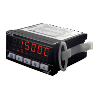
Identifies status display, indicators (A1-A4, Rx/Tx), and keys (PROGRAM, BACK, UP/DOWN, FUNCTION).

Parameter Access Levels

Outlines the different parameter access levels: Work, Alarms, Functions, Configuration, etc.

Configuration Protection

Keypad Lock Operation

Explains how to lock/unlock parameter levels using key combinations.

Programming the Digital Panel Meter

Work Level

The initial level displays PV and alarm setpoints; advance by pressing PROGRAM key.

Alarm Level Parameters

Details parameters for configuring alarm functions (F_URL, Err, Lo, Hi, dF.Lo).

Function Level Parameters

Details parameters for function keys (F.Func, dG.In, Filtr, OFSET, bRud, AdrES).

Configuration Level Settings

Input Signal Configuration

Covers input type, decimal point, temperature unit, scale, and input limits.

Analog Output Configuration

Covers analog output type, low and high retransmission limits.

Customized Linearization Level

Input and Indication Values

Defines input/indication values for custom linearization segments.

Calibration Level

Input and Output Calibration

Sets calibration for Process Variable and Analog Output (offset/span).

Cold Junction & Hardware Type

Calibrates cold junction temperature and adapts firmware to hardware.

Input Calibration Procedures

Step-by-Step Guide

Provides a step-by-step guide for input calibration procedures.

Serial Communication Features

RS485 Interface Features

Lists features of the RS485 interface like compatibility, network distance, etc.

RS485 Interface Electrical Connection

RS485 Signal Lines

Describes bidirectional and inverted bidirectional data lines for RS485.

Serial Communication Registers

Communication Protocol

Details the MOSBUS RTU slave implementation for serial communication.

Holding Register Table

Lists common communication registers for PV, display value, and other parameters.

Device Specifications

Physical and Environmental Data

Details dimensions, power, environmental conditions, and panel cut-out.

Ordering Information

Model and Option Selection

Details model series, relays, analog output, communication, and voltage rating options.