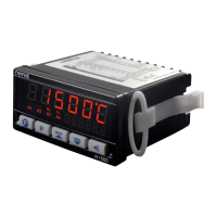
N1500 Digital Panel Meter
NOVUS AUTOMATION 2/8
ALARMS
The digital panel meter has 2 alarm outputs in the basic version and
up to 4 alarms outputs optionally.
Each alarm has a corresponding LED message in the front panel to
show alarm status.
ALARM FUNCTIONS
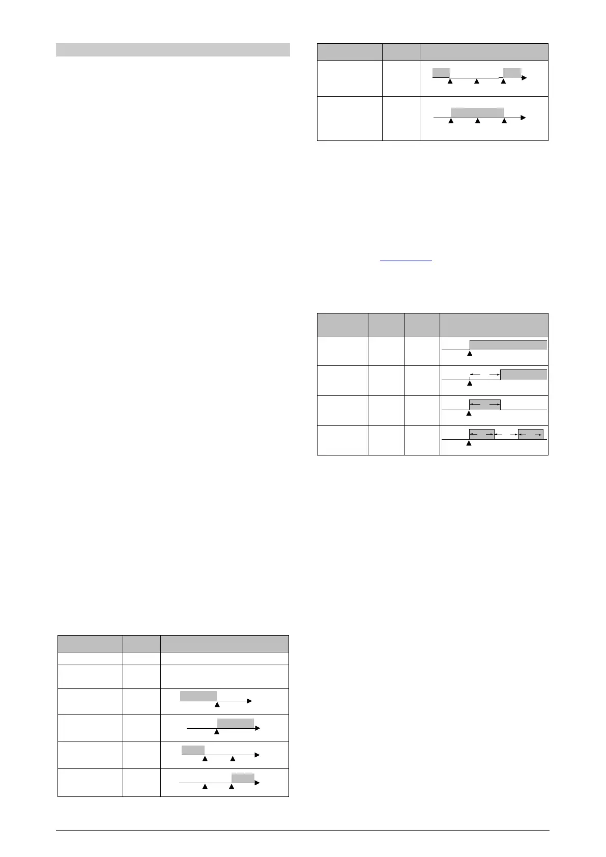
The alarms can be set to operate in seven different modes. These
modes are shown in Table 2 and described below. The alarm can
also be set as ‘disabled’.
• Break alarm -
Ierr
The break alarm is triggered whenever the input sensor breaks or is
badly connected.
• Low alarm -
Lo
The alarm relay is triggered whenever the measured value is below
the alarm set point.
• High alarm -
Ki
The alarm relay is triggered whenever the measured value is above
the alarm set point.
• Differential low –
Dif.lo
Deviation alarm. Alarm relay is triggered whenever the difference
(deviation) between the Process Variable and the reference value
(
AlrEF) is lower than the values defined in SP.AL. For this function,
the triggering point is defined as:
(
ALrEF – SP.AL)
• Differential High –
Dif.ki
Deviation alarm. Alarm relay is triggered when the difference
(deviation) between the Process Variable value and the reference
value (
AlrEF) is greater than the value defined in SPAL. For this
function, the triggering point is defined as:
(
ALrEF + SP.AL)
• Differential (or Band) out of range –
Dif.ov
Deviation alarm. Alarm relay is triggered when the difference
(deviation) between the Process Variable value and the reference
value (
AlrEF) has its modulus greater than the value configured in
SPAL. For this function, the triggering point is defined as:
(
ALrEF – SP.AL) and (ALrEF + SP.AL)
• Differential (or Band) within range –
Dif.In
Deviation alarm. Alarm relay is triggered when the difference
(deviation) between the Process Variable value and the reference
value (
AlrEF) has its modulus lower than the value defined in
SPAL. For this function, the triggering points are defined as:
(
ALrEF – SP.AL) and (ALrEF + SP.AL)
TYPE PROMPT ACTION
Break Alarm
(input Error)
Alarm will go ON if sensor breaks
Low Alarm
(Low)
High Alarm
(High)
Differential Low
(differential Low)
Differential High
(differential High)
TYPE PROMPT ACTION
range
range
(differential
Table 2 – Alarm functions
ALARM TIMER
The alarms can be configured to perform timing functions. The
configuration allows the alarm output to be delayed, or to deliver a
single pulse or a train of pulses. The delay, the pulse width and the
period are defined by the user.
Table 3 shows these advanced functions. Times T1 and T2 can be
programmed from 0 to 6500 seconds and are define during
configuration (see ALARM LEVEL section). Programming 0 (zero) in
the timer parameters T1 and T2 disables the timer function.
The leds associated with the alarm always light up when the alarm
condition occurs, regardless of the current state of the output relay,
which may be de-energized momentarily due to a time delay.
ADVANCED
FUNCTION
T1 T2 ACTION
Normal
Operation
0 0
Delayed 0
1 s to
6500 s
Pulse
1 s to
6500 s
0
Oscillator
1 s to
6500 s
1 s to
6500 s
Table 3 – Timer alarm functions
ALARM INITIAL BLOCKING
The Initial Blocking option inhibits the alarm from being recognized
if an alarm condition is present when the controller is first energized.
The alarm will be triggered only after the occurrence of a non alarm
condition followed by a new occurrence for the alarm.
The Initial Blocking is disabled for the Break Alarm function.


 To Next Page
 Loading...
