9
NL
4
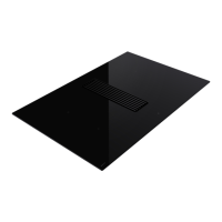
Plak de water
dicht strip op 2mm van de buitenrand
aan de achterkant van de glasplaat
5
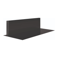
Bocht plaatsen voor afvoerkanaal.
Indien
het afvoerkanaal direct met een bocht naar
beneden wordt gemonteerd, plaats dan eerst
de meegeleverde bocht op de unit. Gebruik
aluminiumtape om de aansluiting luchtdicht te
maken.
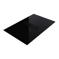
6
Plaats het toestel in de voorziene opening. Neem
de kookplaat links en rechts stevig vast. Kantel
deze lichtjes, zodat eerst de achterzijde in
de openingen past. Laat daarna de voorzijde
voorzichtig zakken. De rest van het kanaalwerk
kan nu aangesloten worden. Volg hiervoor de
beschrijving in hoofdstuk 3.
7
Schakel de hoofdschakelaar of de betr
effende
zekering uit voordat het toestel aangesloten wordt.
Het toestel wordt geleverd met een aansluitkabel.
Sluit deze aan volgens de beschikbare aansluiting.
(zie aansluitschema).
BN: Bruin
BK: Zwart
BU: Blauw
GY
: Grijs
GN/YE: Geel en gr
oen
8
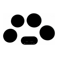
Plaats het vetfilter frame en het afzuigr
ooster in
de aanzuigopening.
FR
4
Collez le ruban isolant à 2 mm du bor
d extérieur
à l’arrière du verre.
5
Installation du coude pour le conduit d’évacuation.
Dans le cas où le conduit d’évacuation est installé
directement avec un coude vers le bas, il faut
d’abord installer le coude fourni sur l’unité. Sur
l’arrière de l’unité se trouve le raccordement
du conduit d’évacuation. Utilisez du ruban en
aluminium pour rendre le raccordement étanche.
6
Po
sez l’appareil dans la découpe prévue.
Maintenez l’appareil des deux côtés. Basculez
la table de cuisson légèrement, afin que le côté
arrière s’encastre en premier dans la découpe.
Ensuite faites descendre le prudemment le côté
avant. Maintenant le conduit peut être raccordé.
Pour cela, il faut suivre les consignes dans le
chapitre 3
7
Couper l’interrupteur principal ou le fusible en
question avant de raccorder l’appareil. L’appareil
est fourni avec un câble de connexion. Connecter
en fonction de la connexion disponible (voir le
schéma de câblage).
BN : Marron
BK : Noir
BU : Bleu
GY : Gris
GN/YE : Jaune et vert
8
Placez le cadre du filtre à graisse et la grille dans
la ouverture d’extraction.
DU
4
Kleben Sie den Isolierstr
eifen in 2 mm Abstand
von der Außenkante auf die Rückseite der Glas-
platte.
5
Umlenkstück für Abluftkanal platzier
en. Wenn der
Abluftkanal direkt in einer nach unten weisenden
90 Grad Bogen montiert wird, bringen Sie zuerst
das mitgelieferte Umlenkstück am Gerät an. An der
Rückseite des Geräts befindet sich der Anschluss
für den Abluftkanal. Verwenden Sie Aluklebeband,
um die Verbindungsstelle luftdicht abzuschließen.
6
S
tellen Sie das Gerät in die vorgesehene Öffnung.
Halten Sie das Kochfeld links und rechts gut fest.
Kippen Sie es leicht, so dass es zuerst mit der
Rückseite in die Öffnungen passt. Lassen Sie
dann vorsichtig die Vorderseite herunter. Jetzt
kann der Kanal angeschlossen werden. Befolgen
Sie hierzu die Beschreibung in Kapitel 3.
7
Schalten Sie den Hauptschalter oder die betr
effende
Sicherung aus, bevor Sie das Gerät anschließen.
Das Gerät wird mit einem Anschlusskabel geliefert.
Schließen Sie es entsprechend dem verfügbaren
Anschluss an (siehe Schaltplan).
BN: Braun
BK: Schwarz
BU: Blau
GY
: Grau
GN/YE: Gelb und Grün
8
Setzen Sie den Fettfilterrahmen und das Gitter in
die Ansaugöffnung.
EN
4
St
ick the insulation strip 2 mm from the outer
edge at the rear side of the glass plate.
5
Install a bend for the exhaust duct.
If the exhaust
duct is mounted directly with a downward bend,
first place the supplied bend on the unit. The
connection for the exhaust duct is on the rear
of the unit. Make the connection airtight with
aluminium tape.
6
Place the unit in the opening pr
ovided. Firmly
hold the cooking plate on the left and the right
sides. Slightly tilt it and place the rear side into
the openings. Then carefully lower the front side.
The duct can now be connected. For this follow
the description in chapter 3.
7
Disable the main switch of the fuse concerned
before connecting the unit. The unit is supplied
with a connection cable. Connect this according
to the available connection (see connection
diagram).
BN: Brown
BK: Black
BU: Blue
GY: Grey
GN/YE: Y
ellow and green
8
Insert the grease filter frame and the grille into
the extraction opening.
 Loading...