6. Power Switch Button— Turn the inverter ON or OFF.
7. Digital Display— Shows input voltage (in volts), output power (in
kilowatts and watts), and error code information. The allowed power
tolerance is 15% (with loads of over 300 W), and the allowed voltage
tolerance is +/- 0.2 V (no load).
8. Cooling Fan and Ventilation Openings— The high-speed cooling
fan protects the inverter from over-heating. Ventilation openings
should be kept clean!
9. 2 GFCI-Protected Outlets—Each GFCI has two AC outlets and is
connected with 20A circuit protector.
10. Two 20A Circuit Protectors
Figure 2: Digital Power Inverter Rear Panel
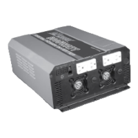
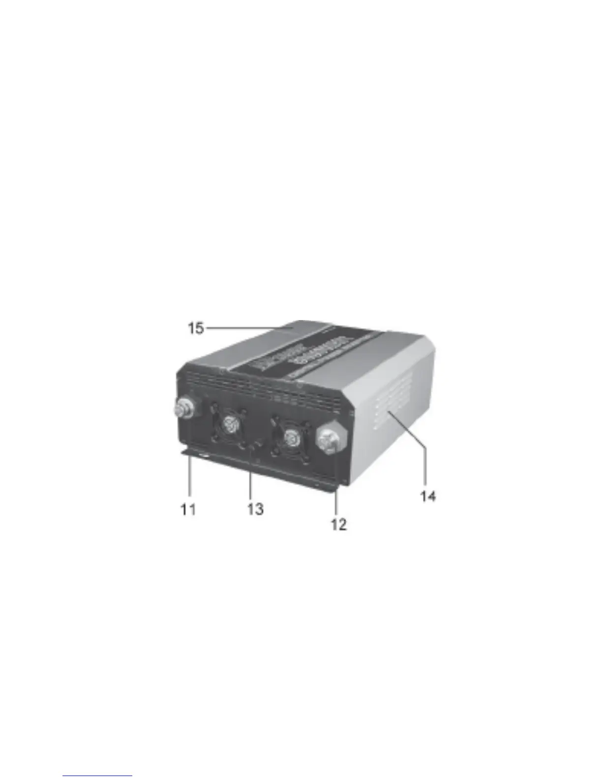
11. Negative (-) DC terminal—Connects to negative battery cable.
12. Positive (+) DC terminal— Connects to positive battery cable.
13. Chassis Ground Lug
14. Ventilation Openings
15. AC Konckout
7
 Loading...