Do you have a question about the NuAire Ecosmart ES-ISC Series and is the answer not in the manual?
| Category | Controller |
|---|---|
| Brand | NuAire |
| Series | Ecosmart ES-ISC |
| Power Supply | 100-240 VAC, 50/60 Hz |
| Operating Temperature | 0 to 50 °C |
| Outputs | Relay outputs, alarms |
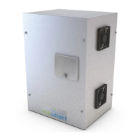
Description of the ES-ISC Ecosmart Speed Control and its compatibility with Nuaire systems.
Guidance on safe offloading, handling, and positioning of the unit modules.
Table detailing the physical dimensions and weights of various ES-ISC control models.
General requirements for competent personnel installation, location, and ventilation.
Procedure for mechanical mounting, including cover removal and fan reconnection.
Crucial safety step: ensure the unit is electrically isolated before commencing mechanical work.
Details on mains power supply, sizing, and connection via isolation switch.
Key practices to reduce EMI, including screened cables and proper earthing.
Instructions for sizing and terminating mains cables to the control terminals.
Details on using IDC plug-in Net connectors for sensors and manual controls.
Explanation of the SL terminal's function for fan activation and over-run.
Wiring instructions for connecting dampers, including delay cancellation.
Best practices for data cable runs to ensure system efficiency.
Specifies the limit of 32 devices that can be connected via the cable.
Information on connecting BMS signals, including voltage tolerance and override behaviour.
Procedure to set maximum airflow using the 'MAX' potentiometer.
Procedure to set minimum airflow using the 'Min' potentiometer.
How to use the test button to check fan operation, with auto-return.
Description of the function and status of various LED indicators on the control panel.
Routine maintenance schedule and steps for cleaning and inspection.
Guidance on ordering spare parts and Nuaire's stock availability.
Details of the 5-year warranty, its coverage, and voidance conditions.
