Do you have a question about the NuAire LabGard ES NU-565-400 and is the answer not in the manual?
| Airflow | 0.38 m/s (75 fpm) inflow, 0.51 m/s (100 fpm) downflow |
|---|---|
| Noise Level | ≤65 dBA |
| Electrical Requirements | 120V, 60Hz, 15A or 230V, 50Hz, 10A |
| Certification | NSF/ANSI 49 |
| Certifications | NSF/ANSI 49 |
| Type | Class II, Type A2 Biological Safety Cabinet |
| Filter Type | HEPA |
| Motor | ECM |
| UV Light Option | Optional |
Explains the scope and content of the manual.
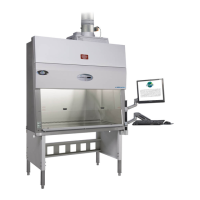
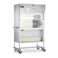
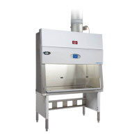
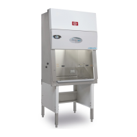
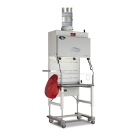
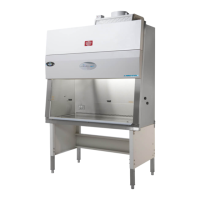
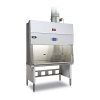
Describes the LABGARD® ES Model NU-565 Laminar Flow Biosafety Fume Hood/Cabinet.
Explains various safety symbols used in the manual.
Specifies the available sizes for the NU-565 model.
Outlines steps for handling shipments with visible or concealed damage.
Provides guidance on ideal placement of the biosafety fume hood/cabinet.
Instructions for assembling the base stand and leveling the cabinet.
Steps for benchtop installation and considerations for gas service.
Details requirements and recommendations for plumbing connections.
Explains electrical connection requirements and recommendations.
Guidelines for installing exhaust and supply air ductwork for the cabinet.
Checks exhaust volume and inflow velocity readings from the front panel.
Describes how the supply volume is controlled and potential alarm causes.
Recommends cabinet certification and outlines initial checklists and tests.
Introduces the Biosafety Fume Hood/Cabinet Control (BSCC) system.
Describes the display and functions available in standby mode.
Explains the operation and display in run mode, including warm-up.
Details how standby/run mode alarms are indicated and lists alarm types by priority.
Shows airflow control setpoints and indicates restricted access.
Lists and describes available timer functions for the cabinet.
Explains how to view downflow and inflow history data.
Accesses a password-protected area for calibration and service.
Allows alteration of LCD screen display features and date/time.
Provides steps to change the user password from the default value.
Displays cabinet model, serial number, and software revision.
Explains the optional night setback feature for reducing exhaust air volume.
Describes the optional remote override feature for controlling cabinet operation.
Covers safe work area, air curtain integrity, and minimizing room activity.
Explains the importance of unidirectional airflow and its disruption.
Stresses the need for aseptic techniques when using the LFBSC.
Steps for starting the cabinet and initial interior disinfection.
Guidance on arranging materials and performing workspace purging.
Details recommended practices for performing work in the cabinet.
Procedures for purging the cabinet and wiping down surfaces post-use.
Covers maintenance of the paper catch and cabinet shutdown procedures.
Discusses the importance of ergonomics for cabinet usage and user health.
Provides general guidelines for cleaning laboratory equipment.
Provides guidance for decontaminating the cabinet after spills or for maintenance.
Details decontamination procedures, including formaldehyde use and safety.
Instructions for replacing the LED lamps in the cabinet.
Explains when and how to replace HEPA filters and motors.
Step-by-step instructions for replacing the supply HEPA filter.
Step-by-step instructions for replacing the exhaust HEPA filter.
Guidance on removing the motor/blower assembly.
Explains the necessity of setup and calibration for certification.
Verifies and sets the cabinet and motor type for system configuration.
Explains verification and alteration of airflow setpoints and alarm limits.
Steps for calibrating exhaust volume without a motorized butterfly valve.
Steps for calibrating exhaust volume with a motorized butterfly valve.
Details the procedure for calibrating the downflow sensor.
Procedure for calibrating the night setback feature.
Instructions for accessing and testing the supply HEPA filter.
Procedures for testing the exhaust HEPA filter using a gross leak method.
Describes how to perform a smoke pattern test to assess airflow.
Verifies installation parameters like sash position and alarms.
Describes testing procedures to assure compliance with cleanliness standards.
Details the components and replacement of the main control board.
Instructions for replacing fuses on the main control board.
Explains the two types of software operating resets available for the cabinet.
Explains the function and replacement of the downflow velocity sensor.
Explains the function and replacement of the exhaust pressure sensor.
Covers error messages, troubleshooting, diagnostics, and sensor verification.
Provides a guide to troubleshoot various error messages and their corrections.
Accesses the service menu for calibration and other tasks.
Manages exhaust damper position and override functions for various conditions.
Allows technicians to view, alter, or reset UV light and blower run timers.
Allows viewing and updating the certification date with reminders.
Sets filter status data to predict filter life availability.
Allows technicians to configure factory setup parameters.
Allows selection of alarm silence key function and times.
Enables/disables interlock features for various cabinet functions.
Provides access to auxiliary relay functions and accessory outlet settings.
Allows technicians to exercise control system diagnostics.
Checks airflow sensors in run mode for responsiveness to airflow changes.
Details relay contacts and their functions for fan, alarm, and auxiliary operations.
Describes contacts for remote override and placing the cabinet into night setback.
Explains the function, operation, and maintenance of the UV light.
Specifies voltage, frequency, phase, and amp requirements.
Defines operational parameters like temperature, humidity, and altitude.
Covers installation category, pollution degree, chemical exposure, and EMC.
Provides guidance on proper disposal and recycling of cabinet components.