Do you have a question about the NuFlo EZ-IN Series and is the answer not in the manual?
Safety and operational guidelines for installing the flowmeter, including line cleaning and avoiding damage.
Step-by-step instructions for fitting the flowmeter between pipeline flanges and connecting components.
Procedure for safely removing and inspecting the flowmeter's internal components for wear or damage.
Detailed steps for correctly reassembling the flowmeter, including lubrication warnings and bearing insertion.
Part numbers and linearity data for precalibrated rotor and bearing support kits for various meter sizes.
Part numbers for hardware kits and centering rings required for raised-face flange installations.
Part numbers for hardware kits specific to ring joint flange connections.
Part numbers for magnetic pickups, categorized by meter size and operating temperature range.
| Model | EZ-IN Series |
|---|---|
| Category | Measuring Instruments |
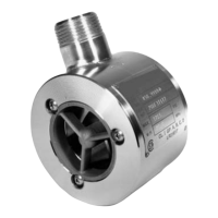
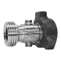
| Type | Flow Meter |
| Accuracy | ±1% of reading |
| Pipe Size | 1/2" to 24" |
| Output Signal | 4-20 mA, pulse, or frequency |
| Material | Stainless Steel |
| Output | 4-20 mA, pulse, or frequency |
| Installation | Insertion |