Do you have a question about the NuFlo MC-II Plus Weatherproof and is the answer not in the manual?
Details internal and external power supply options and battery backup.
Details flow meter frequency, pulse, and 4-20mA outputs.
Provides initial notes for installing panel mount and weatherproof versions.
Explains how the device indicates and reports detected errors.
Outlines calibration steps for liquid volume in predefined units like BBL, GAL, M³.
Outlines calibration steps for gas volume in predefined units like MCF.
Details calibration for custom liquid units using calculated divisor and rate multiplier.
Details calibration for custom gas units using calculated divisor and rate multiplier.
Explains how to set a predefined accumulated volume value.
Details how to adjust the flow rate filter for smoother display.
Details how to enable and configure pulse output parameters.
Explains how to configure the 4-20 mA output for flow rate representation.
Describes how to set up a security code to protect settings.
Describes the three configurations for panel mount units.
Lists the five available input/output features for panel mount units.
Illustrates the wiring connections for the flow meter input.
Lists part numbers for various panel mount MC-II Plus configurations.
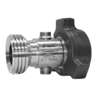
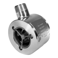
Introduces the weatherproof MC-II Plus Flow Analyzer and mounting options.
Details the procedure for direct mounting to a flow meter.
Explains methods for mounting the unit remotely.
Lists part numbers for various weatherproof MC-II Plus configurations.
Details the process for replacing the unit's lithium battery.
Details the process for replacing the main circuit assembly.
Details the steps for installing the Relay Pulse Output board.
Lists operating temperature, output current, and input power for the relay board.
Diagram showing wiring for the relay pulse output board.
| Category | Measuring Instruments |
|---|---|
| Manufacturer | Cameron |
| Enclosure | Weatherproof |
| Communication Ports | RS-232, RS-485 |
| Application | Flow measurement |
| Power Source | Battery |
| Measurement Range | Varies depending on sensor |
| Operating Temperature | -40 to 60°C |
| Humidity Range | 0 to 100% RH, non-condensing |
| Battery Life | Up to 1 year |