4
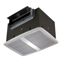
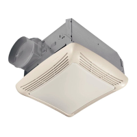
WIRING
Installation work and electrical wiring must be done
by a qualified person(s) in accordance with all ap-
plicable codes and standards, including fire-rated
construction codes and standards.
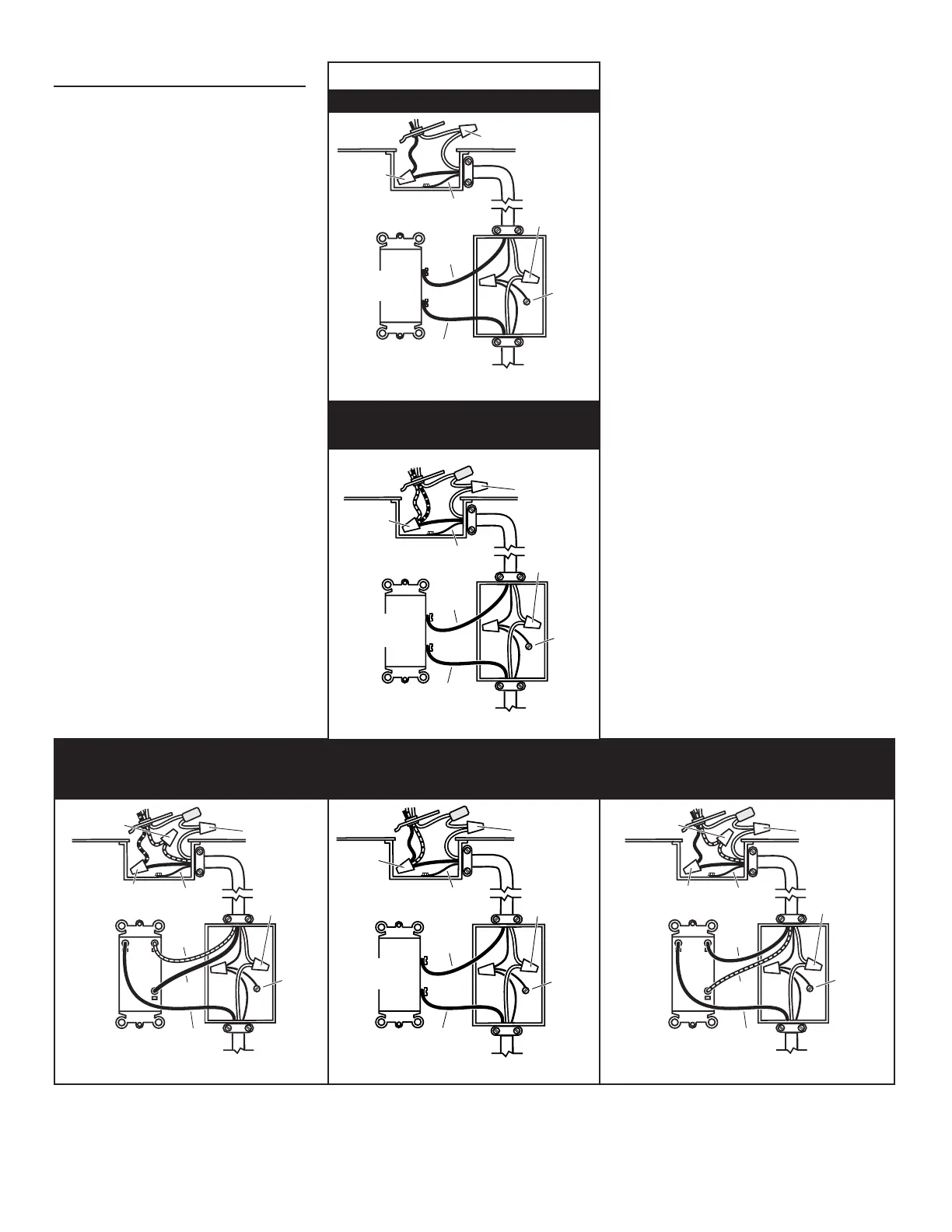
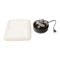
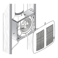
1. Remove wiring box from side of housing. Re-
move knockout(s) and connect power cable(s)
to wiring box using proper U.L. approved con-
nector.
2. Wire unit as indicated in appropriate diagram.
(Fig. 6) Push all wiring into wiring box and replace
wiring box onto housing.
FIG. 6
WHITE to
WHITE / GRAY
120 VAC LINE IN
GROUND
BLACK
BLACK
WHITE
to WHITE
BLACK to
GROUND
120 VAC LINE IN
GROUND
BLACK
BLACK
WHITE to
WHITE
WHITE to WHITE
GROUND
BLACK to
BLACK
SWITCH OR TIMER
MODEL 161
MODEL 162
Lamp & Vent operate together
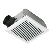
WHITE to
WHITE / GRAY
120 VAC LINE IN
GROUND
BLACK
NEGRO
BLACK
WHITE to
WHITE
BLACK to
BLACK
& RED
GROUND
SWITCH OR TIMER
INTERRUPTOR O
MODEL 163
Lamps operate together
RED
ROJO
VENT
WHITE to
WHITE / GRAY
120 VAC LINE IN
BLACK
BLACK
WHITE to
WHITE
BLACK TO BLUE
RED TO RED
GROUND
HEAT
DUAL CONTROL
GROUND
MODEL 162
Lamp & Vent operate separately
120 VAC LINE IN
GROUND
BLACK
BLACK
LIGHT
BLACK to BLACK
GROUND
HEAT
RED
DUAL CONTROL
RED to RED
WHITE to
WHITE
MODEL 163
Lamps operate separately