5
FINAL ASSEMBLY
1. Protect motor, bulb sockets and wiring from construction
dust, drywall spray, paint, etc. by using the plaster shield. Cut
it from the carton and follow directions printed on it. (Fig. 7)
2. Finish all ceiling work as necessary.
3. Remove plaster shield and check if bottom of housing is
flush with finished ceiling. If not, loosen vertical adjusting
screws, reposition housing, and retighten screws.
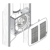
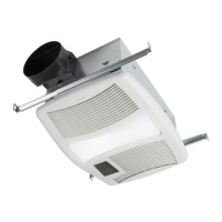
4. Attach grille by hooking springs onto clips on side of
housing. (Fig. 8)
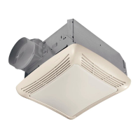
5. Install BR40 or R40-size 250W infrared bulb(s). Center
grille around bulb(s).
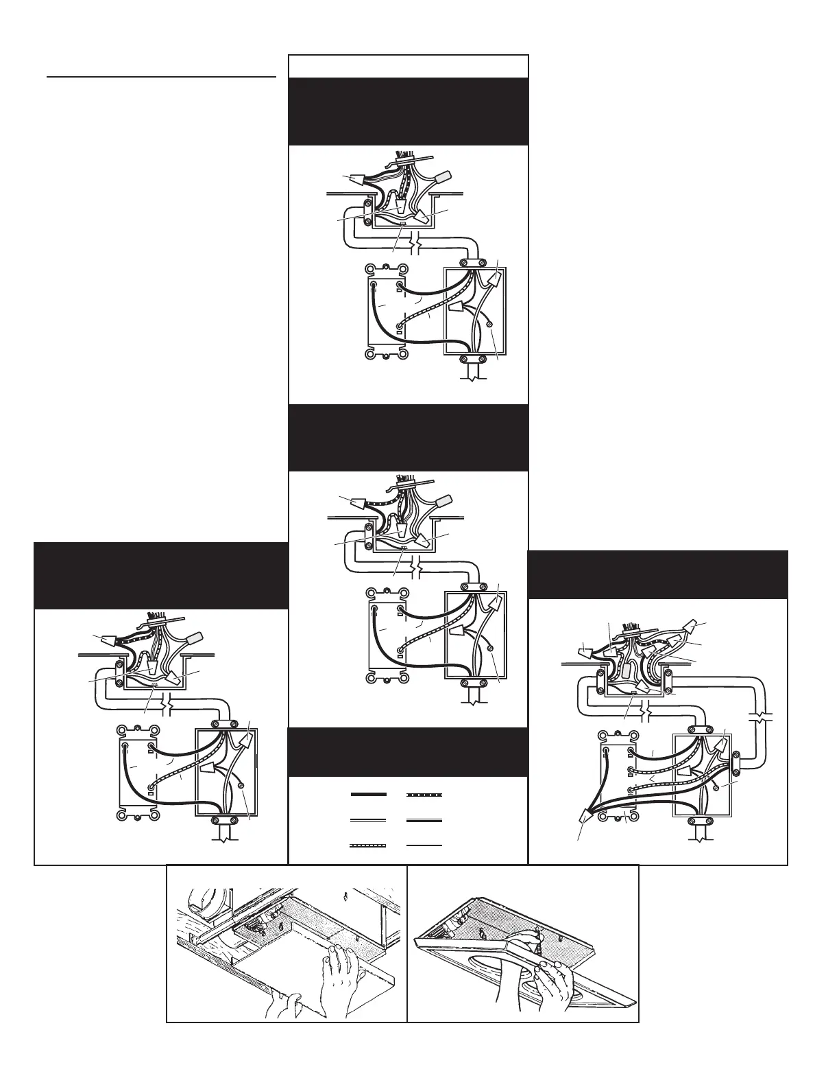
FIG. 6 (CONT')
MODEL 164
Vent & Heat operate together -
Light separately
MODEL
Lamps operate together -
Vent separately
120 VAC LINE IN
DUAL CONTROL
3 WHITE / GRAY WIRES
VENT & HEAT
BLACK to BLACK,
& YELLOW
RED to RED
& BLUE
GROUND
120 VAC LINE IN
DUAL CONTROL
3 WHITE / GRAY WIRES
HEAT & LIGHT
CALEFACCION
y LUZ
BLACK to
BLUE
RED to RED,
BLACK &
YELLOW
GROUND
WIRE COLOR LEGEND
For wiring diagrams
on pages 2 & 3
WHITE
RED
BLACK
BLUE
GROUND
YELLOW
120 VAC LINE IN
DUAL CONTROL
3 WHITE / GRAY WIRES
3 ALAMBRES
HEAT
BLACK to
BLACK, & BLUE
RED to RED
& YELLOW
GROUND
MODEL 164
Light & Vent operate together -
Heat separately
120 VAC LINE IN
GROUND
3 BLACK WIRES
3 WHITE WIRES
LIGHT
BLACK
3-FUNCTION CONTROL
WHITE to WHITE / GRAY
VENT
BLACK to BLACK
BLACK to YELLOW
RED to RED
RED
GROUND
WHITE to WHITE
RED to BLUE
MODEL 164
Light, Vent & Heat operate separately.
FIG. 7
FIG. 8