Do you have a question about the NuTone 655 and is the answer not in the manual?
Safety instructions for Models 655, 659, 659F Heater/Fan/Lights and Models 657, 657F Fan/Lights.
Steps 1-3 for preparing Models 655, 659, 659F, including unplugging and removing components.
Steps 8-13 and 14-17 for installing the heater, covering placement, mounting, and wiring.
Procedures for replacing the bulb, notes on lubrication, and instructions for cleaning the heater.
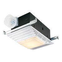
This document describes the installation, operation, and maintenance of the Broan Model 655/659 Heater/Fan/Light and Model 657 Fan/Light units, including finish packs 655F, 657F, and 659F for use with 654H housing packs.
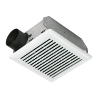
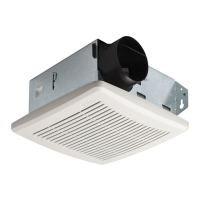
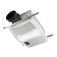
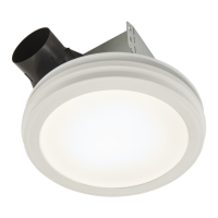
The Broan Model 655/659 is a multi-function unit designed for ceiling installation, providing heating, ventilation (fan), and lighting in one integrated device. The Model 657 is a fan and light combination, also for ceiling installation. These units are intended for indoor use, primarily in bathrooms or similar areas where localized heating, air circulation, and illumination are desired. The heater function (available in Models 655/659) is designed to direct heat towards specific areas like a tub or shower for maximum efficiency. The fan provides ventilation to reduce humidity and odors, while the light offers general illumination.
The units are designed for ease of use and integration into a home environment. For Models 655, 659, and 659F, the heater, fan, and light functions can be operated independently, allowing users to select the desired function(s) as needed. The fan/light models (657 and 657F) provide ventilation and lighting.
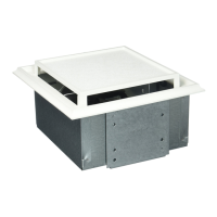
Installation involves mounting the housing between ceiling joists, ensuring the bottom edge is flush with the finished ceiling. The units are designed for ceilings up to a 12/12 pitch, and ductwork for the fan must point upwards. For optimal heating, the heater should be installed to direct heat towards the tub or shower area, avoiding walls or windows. It is crucial to install the heater at least 6 inches from the floor or any adjacent wall. The heater should not be connected to a dimmer switch or speed control. A separate 15 AMP circuit is required for Models 655, 659, and 659F (with 14 GA power cable), and a separate 20 AMP circuit with 12 GA wire for Model 655.
The fan/light models (657 and 657F) are acceptable for use over a bathtub or shower when installed in a GFCI protected branch circuit, offering enhanced safety in wet environments.
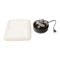
Before initial operation, it is essential to ensure that the heater assembly is properly installed according to the detailed preparation and installation steps provided in the manual. This includes removing the shipping ring from the heater blower inlet before operating the heater. The grille must be installed correctly, with the acorn nut and tooth washer attaching to the threaded rod through the proper hole in the light reflector, to prevent overheating or fire.
To replace the light bulb, the lens can be removed by gently depressing its sides and pulling it down. The units accommodate a bulb rated up to 100 watts.
Regular maintenance is key to ensuring the longevity and safe operation of the device. The manual outlines a simple cleaning procedure that should be performed monthly:
An important note regarding lubrication: the heater is permanently lubricated and does not require oiling or disassembly for lubrication purposes. This simplifies maintenance and reduces the need for specialized servicing.
Throughout the manual, several safety precautions are highlighted to prevent fire, electric shock, or injury to persons. These include:
These guidelines emphasize the importance of proper installation, careful operation, and regular, safe maintenance to ensure the long-term, reliable performance of the Broan heater/fan/light and fan/light units.
| Sound Level | 4.0 Sones |
|---|---|
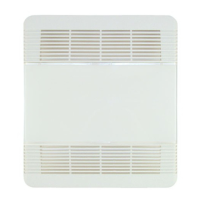
| Grille | Polymeric |
| Blade Span | Not applicable |
| Mounting Type | Ceiling |
| Finish | White |
| Type | Ceiling |
| Duct Size | 4 inch |
| Housing | Steel |
| Material | Metal and plastic |