Do you have a question about the NuTone 668RP and is the answer not in the manual?
Observe safety instructions for fire, electric shock, or injury risks during operation and installation.
Turn off power at the service panel and lock it to prevent accidental activation during maintenance.
Installation and wiring must be performed by qualified persons following all applicable codes and standards.
Ensure sufficient air for combustion and venting of fuel-burning equipment, following NFPA and ASHRAE standards.
Avoid damaging electrical wiring and other hidden utilities when cutting or drilling into walls or ceilings.
Ducted fans must vent outdoors. Unit is acceptable over bathtubs/showers when protected by a GFCI circuit.
Do not use solid-state speed controls. Never place a switch within reach of a tub or shower.
Use a separate 15 AMP circuit and 14 GA power cable that meets code.
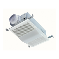
Install only in ceilings, at least 6" from any wall, with ductwork pointing up.
For general ventilation only. Do not use for hazardous or explosive materials.
Keep drywall spray, construction dust, etc., away from the power unit to prevent motor damage.
Always disconnect electric power supply before cleaning or servicing the unit.
Remove lens by depressing sides, pull down. Use bulb rated up to 100 watts.
Clean plastic parts with mild, soapy water. Do not use abrasive cloths or scouring powders.
Support fan assembly when removing screws. Vacuum gently. Motor is permanently lubricated.
Reverse all procedures for reassembly. Do not disassemble further than explained.
Step 1: Remove the lamp holder assembly from the unit.
Step 2: Remove fan assembly retaining screws and lift out the fan assembly.
Step 3: Slide 4 hanger bars into slots on each end of the housing.
Step 1: Position unit between joists, extend brackets, mark keyhole slots flush with ceiling.
Step 2: Remove unit, pound nails partially into joists at marked locations.
Step 3: Hang unit on nails, pound tight. Use screws for wide joists and crimp channels for noise-free mount.
Step 4: Use a flat-bladed screwdriver to remove proper electrical knockouts.
Step 5: Connect electrical wiring as shown in the diagram.
Step 6: Replace fan assembly and plug into receptacle. Direct wires away from blower inlets.
Step 7: Install grille and reflector, plug in light, tighten acorn nut. Install 100W bulb.
Step 8: Gently squeeze tabs on light lens and insert into slots in the grille.
List of numbered parts with part numbers and descriptions for the unit.
Details the one-year warranty, exclusions, disclaimers, and remedy for product defects.
Instructions on how to contact the company for warranty service, including required information.
| Model Number | 668RP |
|---|---|
| Number of Speeds | 2 |
| Width | 30 inches |
| Filter Type | Aluminum |
| Duct Size | 7 inches Round |
| Voltage | 120V |