EasyManua.ls Logo

NuTone 754RBNT User Manual

NuTone 754RBNT
8 pages
To Next Page IconTo Next Page
Page #1 background imageLoading...
Page #1 background image
Page 1
MODELS 754RBNT • 754SNNT
DECORATIVE SERIES
CEILING VENTILATOR
READ AND SAVE THESE INSTRUCTIONS
WARNING
TO REDUCE THE RISK OF FIRE, ELECTRIC
SHOCK, OR INJURY TO PERSONS, OB-
SERVE THE FOLLOWING:
1. Use this unit only in the manner intended by
the manufacturer. If you have questions, con-
tact the manufacturer at the address or tele-
phone number listed in the warranty.
2. Before servicing or cleaning unit, switch power
off at service panel and lock the service dis-
connecting means to prevent power from be-
ing switched on accidentally. When the ser-
vice disconnecting means cannot be locked,
securely fasten a prominent warning device,
such as a tag, to the service panel.
3. Installation work and electrical wiring must be
done by a qualified person(s) in accordance
with all applicable codes and standards, in-
cluding fire-rated construction codes and stan-
dards.
4. Sufficient air is needed for proper combus-
tion and exhausting of gases through the flue
(chimney) of fuel burning equipment to pre-
vent backdrafting. Follow the heating equip-
ment manufacturer’s guideline and safety
standards such as those published by the
National Fire Protection Association (NFPA),
and the American Society for Heating, Refrig-
eration and Air Conditioning Engineers
(ASHRAE), and the local code authorities.
5. When cutting or drilling into wall or ceiling, do
not damage electrical wiring and other hid-
den utilities.
6. Ducted fans must always be vented to the out-
doors.
7. NEVER place a switch where it can be
reached from a tub or shower.
8. This unit must be grounded.
9. This unit is U.L. listed. Type I.C. inherently
protected.
CAUTION
!
1. For general ventilating use only. Do not use
to exhaust hazardous or explosive materials
and vapors.
2. This product is designed for installation in
FLAT CEILINGS ONLY. Do not mount this
product in a wall.
3. The light fixture assembly must be mounted
to the fan housing assembly included with this
product. Do not mount the light fixture as-
sembly to a wiring outlet box.
4. To avoid motor bearing damage and noisy
and/or unbalanced impellers, keep drywall
spray, construction dust, etc. off power unit.
5. Please read specification label on product for
further information and requirements.
TYPICAL INSTALLATIONS
HOUSING MOUNTED
TO ADDITIONAL FRAMING
Discharge 90
0
to joists.
HOUSING MOUNTED
DIRECTLY TO JOIST
2x6 (or larger)
Discharge parallel to joists.
HOUSING MOUNTED
TO 2x4 TRUSS
Requires additional framing
for mounting tabs.
Discharge parallel to joists.
HOUSING MOUNTED TO “I” JOIST
Requires additional framing
for mounting tabs.
Discharge parallel to joists.
HOUSING MOUNTED TO 2x4
TRUSS
Requires additional framing
for mounting tabs.
Discharge 90
0
to joists.
HOUSING MOUNTED TO “I” JOIST
Requires additional framing
for mounting tabs.
Discharge 90
0
to joists.
Installer: Leave this manual with the homeowner.
Homeowner: Use and Care information on page 4.
*
Additional framing must be a 2x6 (minimum height), at least 9-inches long.
*
*
*
*
*

Other manuals for NuTone 754RBNT

Question and Answer IconNeed help?

Do you have a question about the NuTone 754RBNT and is the answer not in the manual?

NuTone 754RBNT Specifications

General IconGeneral
BrandNuTone
Model754RBNT
CategoryFan
LanguageEnglish

Summary

General Safety Warnings

General Safety Warnings

Essential safety precautions for fire, electric shock, and injury risks.

Cautions for Use and Installation

Important cautions regarding unit usage, installation limitations, and maintenance.

Typical Installation Configurations

Housing Mounted Directly to Joist

Illustrates mounting housing directly to a 2x6 joist for parallel discharge.

Housing Mounted to 2x4 Truss (Parallel Discharge)

Shows mounting housing to a 2x4 truss with parallel discharge.

Housing Mounted to "I" Joist (Parallel Discharge)

Demonstrates mounting housing to an "I" joist with parallel discharge.

Housing Mounted to Additional Framing (90° Discharge)

Illustrates mounting housing using additional framing for 90° discharge.

Housing Mounted to 2x4 Truss (90° Discharge)

Shows mounting housing to a 2x4 truss with 90° discharge.

Housing Mounted to "I" Joist (90° Discharge)

Demonstrates mounting housing to an "I" joist with 90° discharge.

Suspended Ceiling Installation

Suspended Ceilings Installation

Describes housing mounting with wires for suspended ceilings.

Housing Installation Procedures

Housing Installation - New Construction

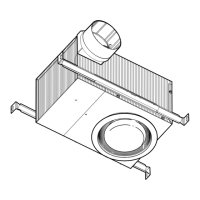
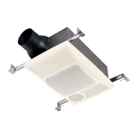
Step-by-step guide for installing housing in new construction.

Housing Installation - Existing Construction

Step-by-step guide for installing housing in existing construction.

Housing Installation - Existing Construction Steps

Details for completing housing installation in existing construction.

Ductwork and Grille Installation

Ductwork Connection and Installation

Steps for connecting and installing the ductwork to the housing.

Grille Pan and Glass Shade Attachment

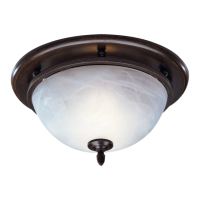
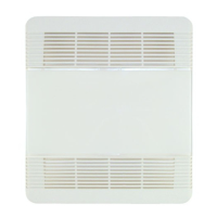
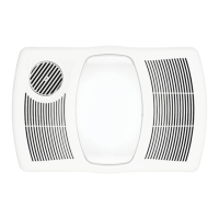
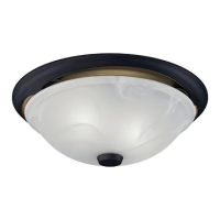
Instructions for attaching the grille pan and glass shade to the unit.

Wiring and Operation

Wiring Diagram and Connection

Schematic and steps for connecting the unit's electrical wiring.

Final Operation Check

Restoring power and checking the unit's operation.

Use and Care Instructions

Bulb Replacement

Procedure for replacing light bulbs in the unit.

Motor Lubrication

Information on the motor's permanent lubrication.

Cleaning Glass Shade and Grille Pan

Guidance on cleaning the glass shade and grille pan.

Cleaning Fan Assembly

Instructions for cleaning the fan motor and interior housing.

Service Parts and Warranty

Service Parts Identification

List of part numbers and descriptions for replacement components.

NuTone One Year Limited Warranty

Details of the limited warranty coverage and terms.

Related product manuals